6
CTR101: Power cable
CTR201: Power / ISOBUS cable
See chapter
on
page 24.
-
10
7
Resistor plug
-
-
8
External alarm signal cable (accessory)
-
1
9
HDC / AUX valve cable (accessory)
2 / 1
1
8
6
4
2
CAN OUT
CAN OUT
8
6
4
2
7
5
3
1
CAN IN
6
3
2
WV1
WV3
P_A
P_B
P_A
WV3
M_B
M_A
PDB
+12V
12 V DC
WV2
P_B
4
1A
7
5
3
1
CAN IN
2
7
5
+12V
9
10
8
!
1B
2
1 PDB2
AUX
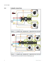
Figure 8. Connection diagram, 4WD.
1A
Control device - master
1B
Control device - slave
Cables
Description
Cable ID
Length [m]
2
Valve cables
WV1 / P_A
WV3 / P_B
PDB / WV2
1
3
Brake signal cable
Brake_sig
10
4
Pressure sensor cables
M_A, M_B
1
5
Display cable + extension
Display
10 + 0.3
6
CTR101: Power cable
CTR201: Power / ISOBUS cable
See chapter
on
page 24.
-
*)
Master / Slave
10
7
Controller link
-
1
8
Resistor plug
-
-
9
External alarm signal cable (accessory)
-
1
10
HDC / AUX valve cable (accessory)
2 / 1
1
*)
In CTR201 control system the master end of the cable connects to the 1A control
device and the slave end of the cable connects to the 1B control device.
Verify the valve solenoid locations from the technical data (see chapter
Control system
Product manual
21


