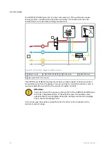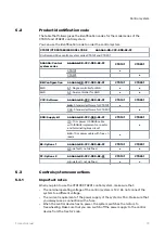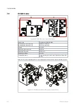
a.
43 mm
2
DW Valve adjustment when the valve is connected to the LS line.*
There is a small gap (2) between the adjustment knob and the locking nut,
although the valve is in the fully closed position.
b.
49 mm
DW Valve adjustment when the LS line is closed with a plug.*
* Tighten the lower nut.
8. Replace the plastic plugs with metal plugs in all the ports that are not in use
(metal plugs are not included in the delivery). Refer to the table of port sizes (see
chapter
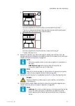
Note:
• If the two-speed function is not in use, plug the Y connection on
the valve.
• CVM120 valve only: If the tractor does not have the LS
connection, plug the LS port on the valve.
Note:
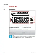
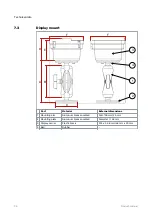
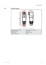
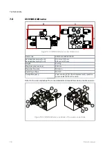
Refer to the technical data for the locations of measurement points,
ports etc. (see chapter
on page 34).
9. Install the control device to an applicable location from the attachment points.
Danger:
Make sure that the system power is not on before you install the
control device.
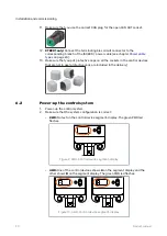
10. Connect all the cables. Make sure that you obey the connection diagram (see
chapter
Control system connection diagrams
Note:
• 4WD only: The control system has two control devices that are the
same. The valve and signal connections set which one of the
control devices is the master device and which one is the slave
device.
Installation and commissioning
Product manual
29


