Hydraulic connections
Y
LS
P
C*
Y
A
A
A
B
B
B
T
C
C*
**
***
Y
**
2
3
4
1
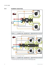
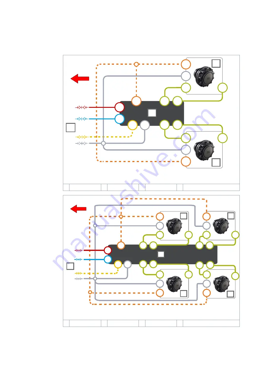
Figure 3. Connection diagram, 2WD.
1 Valve
2 Motor, right
3 Motor, left
4 Hydraulic lines to the tractor
Y
LS
P
C*
Y
A
A
A
B
B
B
T
C
**
B
2
1
C*
A
2
3
3
4
**
A
A
B
B
C*
**
Y
C*
**
Y
Y
***
Figure 4. Connection diagram, 4WD.
1 Valve
2 Motor, right
3 Motor, left
4 Hydraulic lines to the tractor
*
The drain line (C) has a mark (C2) in motors with flushing line (C1).
4.4
System design
14
Product manual


