Installation and commissioning
Installation and the connections
1.
Examine the preferred rotating direction of the hydraulic motors to select the
correct motors for the left and the right side.
2. Install the motors. Refer to the motor manual for the correct installation method.
3. Do not install the wheels at this time. You cannot complete the air-bleeding
procedure if the wheels are installed. When you have completed the air-bleeding
procedure and examined the connections, you can install the wheels.
4. Install the valve to an applicable location from the attachment points.
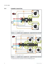
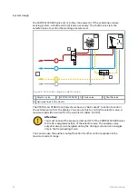
5. Connect the hoses to the valve. Obey to the hydraulic connection diagram (see
chapter
Note:
Be very careful with the drain line (C) connections:
• Make sure that the drain line to the reservoir does not have
pressure.
• If you pressurize the drain line, the hydraulic motor sealings break.
• Mark the hoses. This is very important if the hydraulic supply is in
the tractor.
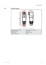
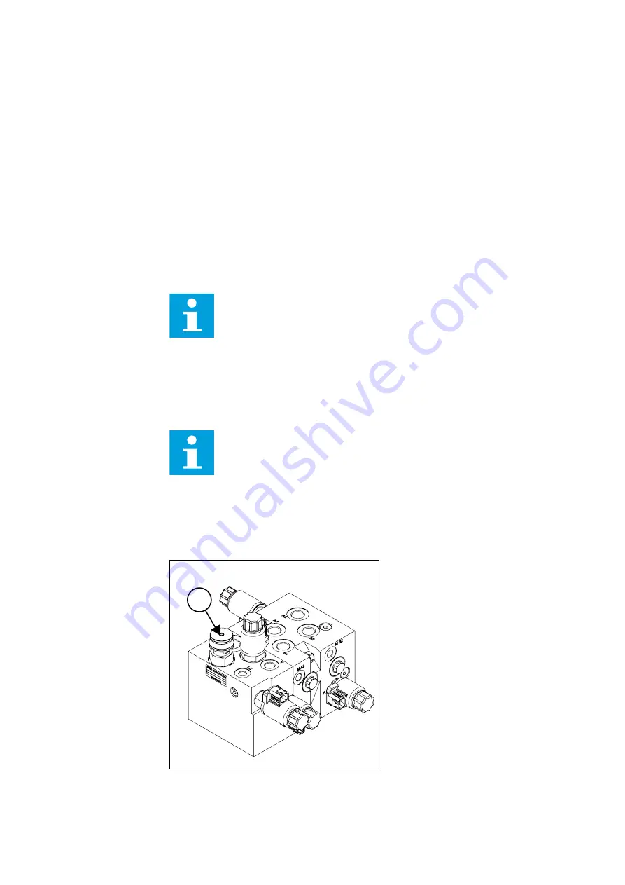
6. Install the system’s pressure sensors (400 bar) to the measurement points M_A2
and M_B2.
Note:
CVM120 4WD models: The valve has two pairs of M_A2 and M_B2
measurement points:
1.
Install the pressure sensors to one of the two pairs.
2. Put the metal plugs on the other pair that is not in use.
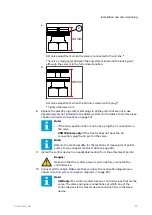
7. CVM120 valve only: Make sure that the DW valve (1) is correctly set. The pump
type and the available connections have an effect on the adjustment. Rotate the
adjustment knob by hand without any tools.
1
6
6.1
Installation and commissioning
28
Product manual

