background image

17

DORNIER DO335.                                                                                           Item code: BH163 


Linkage 

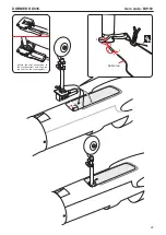
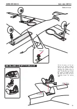
stopper

2mm

secure

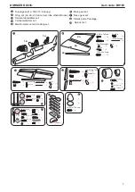
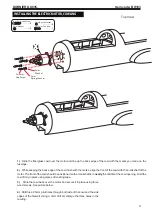
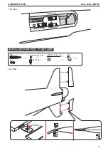
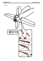
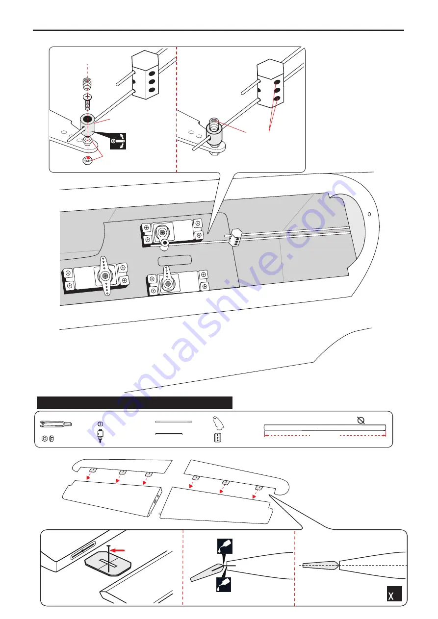
INSTALLING HORIZONTAL STABILIZER

400mm

Aluminium tube.

8mm

M2 

Nut

800 mm Push rod

 - - 2

 - - - 2

  - - - - - - - 2

Horn 

  - - - - - 2

  - - - - - 1

  - - - - - 2

5mm Silicone Tube

  - - - 1

Connector

   - - -  - - 1

Temporary pin to

keep hinge centered.

C.A

C.A

2

Top View

Summary of Contents for BH163

Page 1: ... 2 x 51 x 30 6 mm not included Oleo struts included Spinner 2pcs 80mm SPECIFICATION Length 1 731mm 68 15 in Weight 6 kg 13 2lbs 2 Wing loading 97 72g dm Wing type Naca Airfoil Servo mount 42mm x 21mm Wingspan 1 724mm 67 87in 2 Wing area 61 4dm Radio 06 channels Servo 07 servos Recommended Motor and battery set up not included Motor 2pcs RIMFIRE 55 Lipo cell 6 cells 5 000mAh ESC 2pcs 60A Parts list...

Page 2: ...ad through this manual before starting construction SINCE 1939 Warranty 3 Disclaimer 3 Safety precaution 3 Important building notes 3 Suggestion 3 Flight warnings 3 Covering tools 4 Adhesives and required tools 4 Academy of Model Aeronautics National Model Aircraft Safety Code 4 Part listing not included 6 Tools supplies needed 6 Symbols used throughout this instruction manual comprise 6 Installin...

Page 3: ... the dust will blow back into your eyes Always wear safety goggles a particle mask and rubber gloves when grinding drilling and sanding fiberglass parts Vacuum the parts and the work area thoroughly after working with fiberglass parts IMPORTANT BUILDING NOTES To avoid scratching your new airplane do not unwrap the pieces until they are needed for assembly Cover your workbench with an old towel or ...

Page 4: ...luding fuel of 55 pounds unless in compliance with the AMA Large Model Airplane program AMA Document 520 A f Ensure the aircraft is identified with the RYAN and address or AMA number of the owner on the inside or affixed to the outside of the model aircraft This does not apply to model aircraft flown indoors g Not operate aircraft with metal blade propellers or with gaseous boosts except for helic...

Page 5: ...cuments 922 and 923 6 With the exception of events flown under official AMA Competition Regulations excluding takeoff and landing no powered model may be flown outdoors closer than 25 feet to any individual except for the pilot and the pilot s helper s located at the flightline 7 Under no circumstances may a pilot or other person touch an outdoor model aircraft in flight while it is still under po...

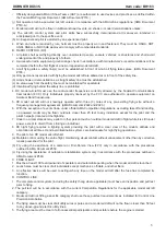
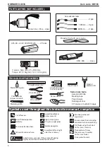
Page 6: ...u will lose control of your aircraft Symbols used throughout this instruction manual comprise Use a pencil to mark Wire cutters Hex Wrench Threadlocker screw cement Hand or electric drill cm 1 2 3 4 5 6 7 8 9 10 Straight edge ruler Some more tools Assorted drill bits Masking tape Paper towels Rubbing alcohol 90 square or builder s triangle Screw driver Medium C A glue EPOXY A EPOXY B 30 minute epo...

Page 7: ...Push rod 4 4 4 Horn 4 4 Flaslink 4 5mm Silicone tube 2x10mm Tp Screw 16 2a 2a 2c M2 Nut 800 mm Push rod 2 2 2 Horn 2 1 2 5mm Silicone Tube 1 Connector 1 M2 Nut 800 mm Push rod 2 2 2 Horn 2 2 5mm Silicone Tube 1 Connector 1 3mm Washer 8 3 x 15mm Cap Screw 8 3 x 12mm Tp Screw 7 3mm Spring Washer 8 85mm Wheels 2 5mm Colar 5 x 35mm Cap Screw 2 3x15mm Tp Screw 8 5mm Washer 2 3 x 15mm Screw 4 3 x 6mm Bu...

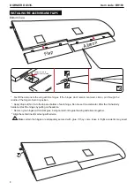
Page 8: ... pin through the middle of the hinge to hold it in position Align the center line of main wing with aileron Secure nylon hinges with instant glue being careful not to glue the wing and aileron together Make certain the hinges are adequately secured with glue if they come loose in flight accidents may WARNING Flap Aileron result DORNIER DO335 Item code BH163 8 INSTALLING THE AILERONS AND FLAPS Temp...

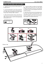
Page 9: ...provided with the servo 5 Place the servo into the servo tray hatch into the servo box on the bottom of the wing and drill 1 5mm pilot holes through the tray and servo box for each of the four mounting screws Secure the servo tray in place using the mounting screws provided DORNIER DO335 Item code BH163 9 4 Using the thread as a guide and using masking tape tape the servo lead to the end of the th...

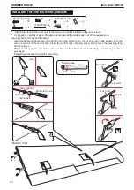
Page 10: ... down through the hole in the control horn Install one nylon snap keeper over the wire to secure it to the control horn Install the control horn retaining screw and remove the masking tape from the aileron Repeat the procedureto install the other wing M2 2mm Nut 100mm Push rod 4 4 4 Horn 4 4 Flaslink 4 5mm Silicone tube DORNIER DO335 Item code BH163 10 2x10mm Tp Screw 16 INSTALLING THE CONTROL HOR...

Page 11: ...both side of the cowl and the side edges of the firewall Using a 3mm drill bit enlarge the three holes in the cowling 2 While keeping the back edge of the cowl flush with the marks align the front of the cowl with the crankshaft of the motor The front of the cowl should be positioned so the crankshaft is in nearly the middle of the cowl opening Hold the cowl firmly in place using pieces of masking...

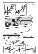
Page 12: ...DORNIER DO335 Item code BH163 12 2 5mm 2 5mm 3x12mm Tp Screw Left Right 2 5mm 3x12mm Tp Screw Top View ...

Page 13: ...ough both side of the cowl and the side edges of the firewall Using a 3mm drill bit enlarge the four holes in the cowling DORNIER DO335 Item code BH163 13 3x15mm Cap Screw 3mm Washer 3mm Spring Washer 2 5mm 3x12mm Tp Screw Left Top View ...

Page 14: ...rass collets into the elevator rudder and throottle servor Test fit the servos into the servo tray Trim the tray if necessary to fit your servos 2 Mount the servo to the tray using the mounting screws provided with your radio system o 90 o 90 approx 16mm 2mm 2mm 2mm For Throttle Servo For Rudder Elevator Servo 1 2 3 4 Top View ...

Page 15: ...od 2 2 2 Horn 2 2 5mm Silicone Tube 1 Connector 1 DORNIER DO335 Item code BH163 15 Rudder servo Elevator servo Nose gear servo INSTALLING VERTICAL STABILIZER Temporary pin to keep hinge centered C A C A 2 Top View Top View ...

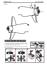
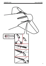
Page 16: ...16 DORNIER DO335 Item code BH163 M2 Metal Clevis Silicon tube 2mm Hex Nut Push rod Control Horn Horn 2 B Cut Silicone tube 5mm ...

Page 17: ...code BH163 Linkage stopper 2mm secure INSTALLING HORIZONTAL STABILIZER 400mm Aluminium tube 8mm M2 Nut 800 mm Push rod 2 2 2 Horn 2 1 2 5mm Silicone Tube 1 Connector 1 Temporary pin to keep hinge centered C A C A 2 Top View ...

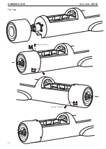
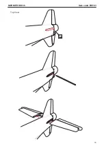
Page 18: ...18 DORNIER DO335 Item code BH163 Top View ...

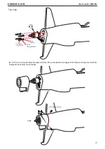
Page 19: ...19 DORNIER DO335 Item code BH163 M2 Metal Clevis Silicon tube 2mm Hex Nut Push rod Control Horn Horn 2 B Cut Silicone tube 5mm Top View ...

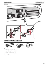
Page 20: ...modeling knife carefully remove the film covering from the wing gear tray Make sure that you do not remove any wood 20 DORNIER DO335 Item code BH163 Linkage stopper 2mm secure INSTALLING THE WHEEL WELL Top View ...

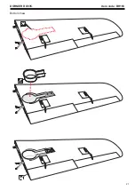
Page 21: ...DORNIER DO335 Item code BH163 21 C A Bottom View ...

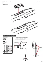
Page 22: ...WO OPTIONS OPTION 1 FIXED GEAR 85mm Wheels Secure 5x35mm 5mm Collar 5mm Washer DORNIER DO335 Item code BH163 22 C A INSTALLING MAIN GEAR 2 5mm Colar 5 x 35mm Cap Screw 2 3x15mm Tp Screw 8 5mm Washer 2 Bottom View ...

Page 23: ...DORNIER DO335 Item code BH163 23 3x15mm Tp Screw Bottom View ...

Page 24: ...Item code BH163 24 OPTION 2 ELECTRIC GEAR RETRACTS Electric not included 43 70 30 70 41 00 51 00 4 20 30 60 92 20 24 10 48 50 2 50 9 75 5 10 21 00 12 00 3x15mm Tp Screw 5x35mm 5mm Collar 5mm Washer Secure Bottom View ...

Page 25: ...TALLING NOSE GEAR 3 x 15mm Screw 4 3 x 6mm Button Screw 1 Spring 1 5mm Washer 1 5 x 35mm Cap Screw 1 1 5mm Colar 600mm Cable 2 2 M3 4 2 2 3mm Nut 65mm Wheels THERE ARE TWO OPTIONS OPTION 1 5mm Washer 5mm Colar 5x35mm Cap Screw Bottom View ...

Page 26: ...OPTION 2 ELECTRIC GEAR RETRACTS DORNIER DO335 Item code BH163 1 2 3 4 5 Cable rod 3x15mm Tp Screw Spring 3x6mm 5mm Washer 5mm Colar 5x35mm Cap Screw 26 Bottom View ...

Page 27: ...Secure the strut suspension to the electric retract and slide the two cable to the steering plate DORNIER DO335 Item code BH163 1 2 3 4 5 Cable rod 27 ...

Page 28: ...old the foam in place Do not permanently secure the receiver and battery until after balancing the model 3 Position the battery pack and receiver behind the fuel tank Use two tie wraps to hold the battery and receiver securely in place as pictures below 4 Using a 2mm drill bit drill a hole through the side of the fuselage near the receiver for the antenna to exit DORNIER DO335 Item code BH163 Rece...

Page 29: ...inium tube dihedral brace into each wing haft The brace should slide in easily If not use 220 grit sand around the edges and ends of the brace until it fits properly Attach the aluminium tube into the fuselage DORNIER DO335 Item code BH163 INSTALLING THE WING TO THE FUSELAGE 29 Top View ...

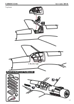
Page 30: ...ar frame on the canopy is aligned with the rear edge of the cockpit opening Use canopy glue to secure the canopy to the canopy hatch Use low tack tape to hold the canopy in position until the glue fully cures Wrap the tape completely around the canopy hatch Open close Open close B 30 Bottom View ...

Page 31: ...Adhesive tape Air intake DORNIER DO335 Item code BH163 B PLASTIC PARTS OF FUSELAGE C A C A C A 31 Top View ...

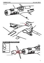
Page 32: ... 8 2 2 DORNIER DO335 Item code BH163 C A C A Air intake C A INSTALLING THE PROPELLER 3x12mm TP Scew 3x12mm TP Scew 32 Top View ...

Page 33: ...DORNIER DO335 Item code BH163 3x12mm TP Scew 33 Top View ...

Page 34: ...n we recommend If possible first attempt to balance the model by changing the position of the receiver battery and receiver If you are unable to obtain good balance by With the wing attached to the fuselage all parts of the model installed ready to fly and empty fuel tanks hold the model at the marked balance point with the stabilizer level High 10 mm up down Low 25 mm left right Control throwAile...

Page 35: ... Use a sharp Suggestion secewdriver to take the red cable out from only one ESC the BEC connector and then insulate it with a bit of electrical tape for futher use Tak e the red line out Motor Motor Receiver Battery E S C E S C 35 ...

Page 36: ...DORNIER DO335 Item code BH163 EXPL ODED VIEW 36 ...

Page 37: ...DORNIER DO335 Item code BH163 37 44mm 41mm 51mm 31mm GEAR MOUNT NOSE GEAR MAIN GEAR 172mm 65mm 13mm 5mm 85mm 158mm 13mm 5mm GEAR DIMENSIONAL DETAIL ...

Page 38: ... up areas DO NOT dispose of empty fuel containers on a fire this can lead to an explosion NEVER fly in wet conditions or on windy or stormy days NEVER use damaged or deformed propellers or spinners THE PROPELLER IS DANGEROUS Keep fingers clothing ties shirt sleeves scarves or any other loose objects that could be caught or drawn in away from the propeller Take care at ALL times Keep all onlookers ...

Page 39: ...model lands at the slowest possible speed Switch on the transmitter OFF ON OFF ON Check that the wings are correctly fitted to the fuselage If the model does not respond correctly to the controls land it as soon as possible and correct the fault Empty the fuel tank after flying fuel left in the tank can cause corrosion and lead to engine problems Check that the transmitter batteries have adequate ...

Reviews: