background image

9

Shock/Page -

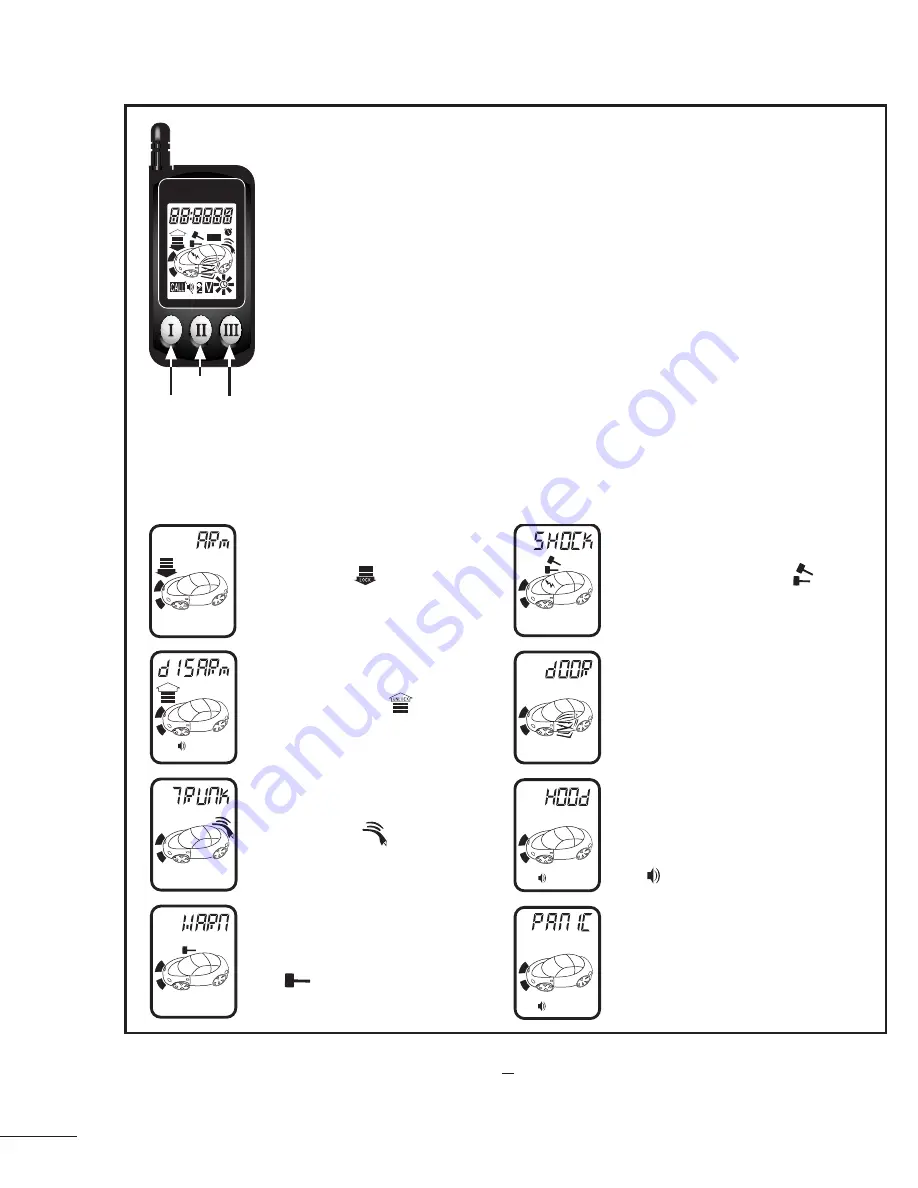
The display will show Shock 
and flash the animated      icon 
to indicate shock sensor
triggering.

Hood -

If the hood or trunk is opened 
while the system is armed, the 
display will show HOOD and 
the     icon will be displayed.

UNLOCK

LOCK

O.K.

Arm

Start

Confirm

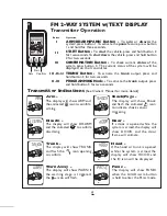
FM 2-WAY SYSTEM w/ TEXT DISPLAY

Transmitter Operation

Button

I

II

III

III

Hold

+

Operation

ARM/DISARM/PANIC Button - 

To 

arm

 or 

disarm

 the 

system, press button 1. To activate the 

panic

 feature, press button 

1 and hold for three seconds.

TRUNK Button - 

To activate the 

trunk

 output, press and 

hold button 3 for two seconds.

II

III

+

PROGRAMMING Mode - 

To activate the 

trunk

 output, press 

and hold button 3 for two seconds.

CONFIRMATION Button - 

To check current 

status

 of the 

system, press button 3.  The current status of the system will be 

displayed on the transmitter.

Transmitter Indications

START Button - 

To 

start

 the vehicle, press and hold button 2 

for two seconds. To 

shut down


the vehicle, press and hold button 

2 for two seconds.

Arm -

The display will show ARM and 
the animated       icon to confirm 
arming.

LOCK

Door -

If a door is opened while the 
system is armed, the display will 
show DOOR, and the door 
frame will animate.

Disarm -

The display will show DISARM 
and the animated        to confirm 
disarming. 

UNLOCK

Warn Away -

The display will show WARN if 
the warning stage is triggered, 
the       icon will flash.

Trunk -

The display will show TRUNK 
and flash the       icon opening 
to confirm

Panic -

The display will show PANIC 
when the Arm/Disarm button 
is held to enter the Panic mode.

(See Owner’s Manual for more details)

Summary of Contents for 250

Page 1: ... inside a garage or being left for service Always notify service personnel that the vehicle is equipped with a Remote Starter Only start the vehicle in a well ventilated area Do not use in a closed garage or indoors ITEMS SUPPLIED WITH THE SYSTEM Main unit One 3 button remote control w LCD text display and background illumination Plug In LED Plug in program switch Harness kit with 2 heavy duty fus...

Page 2: ...low proper operation an optional vacuum switch can be installed The vacuum switch is designed to be placed in line with one of the vehicle s vacuum hoses and provide a ground output N C until the engine is started To use the vacuum switch set dip switch 2 to the off position Connect the yellow wire 3 pin red connector to one terminal of the vacuum switch and connect the other terminal to ground Hi...

Page 3: ...ey is turned off GRAY WIRE Tach Spark sense wire If the current sensing feature does not allow desired operation connect the GRAY wire directly to the vehicle s tach wire or negative fuel injector wire and set dip switch 4 to OFF If the tach wire is not accessible wrap the GRAY wire around a spark plug wire or coil wire several times and secure with electrical tape GREEN WIRE Negative door trigger...

Page 4: ...e from the driver s position 2 PinWhite Connector Plug in connector port for horn honk dome light harness WHITE YELLOW horn output RED BLACK Dome light output 5 Pin Antenna Connector Plug in connector port for extended range receiver Plug harness into 5 pin connector route cable up pillar post place double sided tape on flat side of receiver module and place in corner of windshield 4 Remote Progra...

Page 5: ...to Re arm enabled Off Auto Re arm disabled Program 4 Normal Silent Arming On Normal operation Off Silent operation Program 5 Door Unlock Pulse On Single Off Double Program 6 Door Lock Pulse Length On 0 7 second door lock unlock pulse Off 3 second door lock unlock pulse Program 7 Ignition Lock On Ignition auto lock Off No ignition auto lock Program 8 Auto Cold Start Defeat On Disable Auto Cold Capa...

Page 6: ...ll still operate To enter valet mode 1 Turn ignition to the on position 2 Within 5 seconds press and hold program switch for approximately 2 seconds The LED will light solid Parking lights will flash once The siren will chirp once To exit valet mode 1 Turn ignition to the on position 2 Within 5 seconds press and hold program switch for approximately 2 seconds The LED will turn off Adding or Deleti...

Page 7: ...icator in the instrument cluster To properly interface into these systems and retain full functionality of the factory anti theft system use the APV 1 module The Passkey 3 system which is found on GM vehicles 1999 and newer is a transponder based system described below Use the APP 1 module to integrate into Passkey 3 equipped vehicles This module allows full functionality of the factory anti theft...

Page 8: ...UTPUT RED CONNECT EACH DIRECTLY TO THE BATTERY See page 2 GREEN DOOR TRIGGER VIOLET DOOR TRIGGER BLACK GROUND INPUT ORANGE ARMED OUTPUT GROUND WHEN RUNNING WHITE PARKING LIGHT OUTPUT RED 12V INPUT HOOD SWITCH INPUT BLUE BROWN SIREN OUTPUT GRAY TACH SPARK SENSE VIOLET STARTER OUTPUT ORANGE ACCESSORY OUTPUT YELLOW BRAKE SWITCH INPUT BLUE GREEN RED UNLOCK 12V LOCK 1 2 3 4 DIP SWITCH SETTINGS Default ...

Page 9: ...CONFIRMATION Button To check current status of the system press button 3 The current status of the system will be displayed on the transmitter Transmitter Indications START Button To start the vehicle press and hold button 2 for two seconds To shut down the vehicle press and hold button 2 for two seconds Arm The display will show ARM and the animated icon to confirm arming LOCK Door If a door is o...

Page 10: ...is not working Use either the spark sense or tach sense Vehicle has a factory theft deterrent system that prevents starting w o key in ignition Suggested Correction Main Inputs heavy gauge red wires and small red wire on main harness must be connected to 12V Turn ignition key to on position press and hold service switch for 5 seconds The LED will turn off Check Brake Switch Input Yellow Wire or Ho...

Page 11: ...sitive voltage GREEN wire is connected to ground main YELLOW wire ignition wire is connected to 12V or door pin switch is bad Bad connection on WHITE wire or the output polarity is wrong for the circuit being driven Defective GREEN or BLUE wire from door lock connector plug GREEN and BLUE wires reversed or wrong door lock wiring diagram used Suggested Correction RED wire should connect directly to...

Page 12: ...KING LIGHTS MOST JAPANESE VEHICLES TRUNK RELEASE CIRCUIT DIAGRAM ADDED RELAY TO PREVENT GRINDING STARTER AFTER REMOTE AUTO START TOTRUNK RELEASEWIRE 12V GREEN BLACK WIRE ORANGEWIRE MAIN HARNESS CUT X TO BATTERY TO STARTER MOTOR IGNITION SWITCH PURPLE WIRE HEAVY GAUGE 87 87a 86 30 85 87 87a 86 30 85 87 87a 86 30 85 87 87a 86 30 85 87 87a 86 30 85 87 87a 86 30 85 87 87a 86 30 85 87 87a 86 30 85 87 8...

Reviews: