background image

8

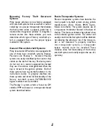
Bypassing Factory Theft Deterrent
Systems

Many newer vehicles are now factory-equipped
with anti-theft systems that use either a resistor
coded key or a passive transponder that disables
the fuel system unless a properly coded key is
inserted into the ignition cylinder. To integrate a
remote starter into these vehicles, you must
determine which type of factory anti-theft sys-
tem is equipped, then use the proper bypass
module for that system.

General Motors Anti-theft Systems:

Many late-model GM vehicles are equipped with
one of three basic anti-theft systems; Passkey,
Passlock, and Passkey 3. Standard Passkey
systems are easily identified by the resistor chip
visible on the shaft of the key. Passlock systems
do not rely on a resistor equipped key. Instead
they use a resistance code generated when the
key is turned in the ignition cylinder. Both of
these systems have an anti-theft indicator in the
instrument cluster. To properly interface into
these systems and retain full functionality of the
factory anti-theft system, VATS/PASSLOCK
bypass module must be installed.

The Passkey 3 system, which is found on GM
vehicles 1999 and newer, is a transponder based
system described below.

Passive Transponder  Systems:

Passive transponder systems have become the
most popular anti-theft system among vehicle
manufacturers (Ford, Honda, BMW, Toyota,
Nissan and others). This system requires use of
a tiny passive transmitter housed in the base of
the key. This device activates when placed close
to the vehicle’s ignition switch. The starter will
usually crank but the fuel system will be disabled,
not allowing the vehicle to run, if the transpon-
der is not detected. To properly interface
into transponder systems, a transponder
bypass module must be installed. These
modules allow full functionality of the factory
anti-theft system and usually require the use of a
spare key.

Summary of Contents for 6150

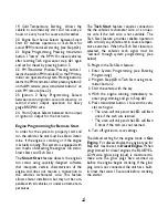
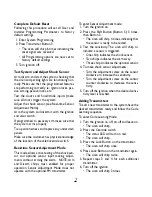
Page 1: ...g the product verify with the customer the desired location for the valet switch and LED Set the Polarity Jumper inside the main unit first see Jumper Settings Installation Instructions Mounting System Module Mount the system module under the dash where it will be difficult for a potential thief to locate the module and away from moving parts such as brake pedals etc Mount the extended range recei...

Page 2: ...art feature fails to start properly connect the BLACK GRAY wire directly to the vehicle s tach wire or negative fuel injector wire and program Step 20 toTach Start WHITE RED WIRE Auxiliary 2 output 500mA Connect to a relay or module for an optional feature such as power window activa tion or remote start etc This output may be programmed for momentary timed or latched operation BLACK WHITE WIRE Do...

Page 3: ... WHITE WIRE Parking Light output 10A relay Connect to the vehicle s parking light wire If the vehicle s parking light circuit exceeds 10 Amps a relay is required For vehicle s with independent left and right parking light circuits the parking light wires must be connected using diodes to keep the circuits separate NOTE Do not connect the WHITE wire to the vehicle s headlight circuit BROWN WHITE WI...

Page 4: ...ry 2 hours Every hour 20 Engine Start Sense Smart Start Tach Start 21 Engine Programming Learn RPM Gas Engine Diesel Engine 22 FM Module Program optional Learn Module Learn FMTransmitter 23 Ignition 2 Relay Programming Ignition 2 Accessory 2 Starter 2 24 Horn Output Horn Output Ignition 3 Output Entering Programming To enter System Programming 1 Turn on ignition 2 Within 5 seconds press valet swit...

Page 5: ... for 15 seconds allowing access to the emergency override switch Only delays when the system is armed passively 10 Bad Zone Report Siren will chirp 3 times if any zone remains open 5 seconds after arming If vehicle has delayed dome light program this feature to OFF 11 Auxiliary 2 Auto Activate on Arming When selected the Auxiliary 2 output will pulse upon system arming to activate accessory items ...

Page 6: ...terprets certain characteristics of the engine and does not require a connection to the vehicle s tachometer wire This feature allows a faster installation but may not be com patible with all vehicles or under extreme tem peratures The Tach Start feature requires connection the the vehicle s tachometer wire or an injec tor wire if the tach wire is not available The Tach Start feature provides reli...

Page 7: ...ing the alarm NOTE Arm and Disarm chirps must enabled for proper operation Sensor Adjustment Mode does not operate with the optional FM transmitter To enter Sensor Adjustment mode 1 Turn the ignition on 2 Press the Shift Button Button 5 3 times then Button 3 The siren will chirp 4 times indicating that the sensor is ready to be tested 3 Test the sensitivity The siren will chirp to indicate a senso...

Page 8: ...gnition cylinder Both of these systems have an anti theft indicator in the instrument cluster To properly interface into these systems and retain full functionality of the factory anti theft system VATS PASSLOCK bypass module must be installed The Passkey 3 system which is found on GM vehicles 1999 and newer is a transponder based system described below PassiveTransponder Systems Passive transpond...

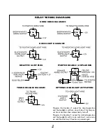
Page 9: ...uxiliary 2 output for timed operation and the headlights will turn on with Aux 2 for the pre set timer duration then automatically turn off Program the Auxiliary 2 output for latched operation and the headlights will turn on with Aux 2 and remain on until the Auxiliary 2 function is pressed again NEGATIVE GLOW PLUG DOME LIGHT DIAGRAMS ...

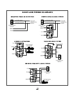
Page 10: ...10 NEGATIVE PULSE LOCK SYSTEM POSITIVE PULSE LOCK SYSTEM ADDING ACTUATORS VACUUM LOCK SYSTEM DOOR LOCK WIRING DIAGRAMS REVERSE POLARITY LOCK SYSTEM ...

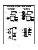
Page 11: ...11 TWO STEP UNLOCK NEGATIVE PULSE TWO STEP UNLOCK POSITIVE PULSE TWO STEP UNLOCK REVERSE POLARITY TWO STEP UNLOCK ADDING ACTUATORS OPTIONAL TWO STEP UNLOCK WIRING DIAGRAMS ...

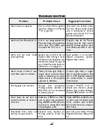
Page 12: ... connected Wrong polarity selected or RED Wire 1 not connected to battery power Defective GREEN or BLUE wire in door lock connector plug GREEN and BLUE wires reversed or wrong door lock wiring diagram used External relay required or Wrong polarity wired for relay Suggested Correction Take alarm out of Valet mode Turn key off and verify yellow wire is connected to correct ignition wire Check 12V an...

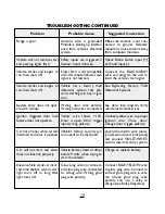
Page 13: ...rity Wrong lock wires connected Yellow wire shows 12V Door is open Door trigger input wrong polarity Vehicle s factory security sys tem needs to be disarmed Vehicle battery dead or drops below 9 volts when trying to start the vehicle Glow plug wire not connect ed Glow plug wire connected to wrong wire Wrong glow plug wire polarity Suggested Correction Make sure antenna is not con nected to ground ...

Page 14: ...Flashes Door Trigger 5 Flashes Hood Trunk LEDTAMPER ALERT INDI CATIONS 1 Flash Optional Sensor 2 Flashes Shock Sensor 4 Flashes Door Trigger 5 Flashes Hood Trunk PARKING LIGHTS FUNC TIONS Flash 1x Armed Flash 2x Disarmed Flash 3x Open Zone Indication after arming Flash 3x after Disarm Tamper Alert INSTALLATION NOTES ...

Page 15: ...15 INSTALLATION NOTES ...

Page 16: ...light relay is deter mined by the placement of the jumper on the 3 pins in front of the relay The default settings is illustrated on the left Jumper on Center Pin and Left Pin Positive Output Jumper on Center Pin and Right Pin Negative Output 2002 DLC INC 64 6150 7150 12 02 Rev 2 ...

Reviews: