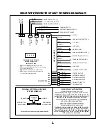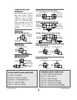
• GRAY WIRE - Ground When Running Output (-).
Connect to a relay for starter anti-grind protection.
(See installation diagrams).
The GRAY wire
provides ground for starter anti-grind protection
and when the remote start is engaged to activate
an optional factory security bypass module. When
the Stop-and-Go mode is engaged, the output will
turn on and remain active even after pressing the
brake pedal. Although the remote start shuts down
when the brake pedal is pressed, the output will
remain on until the ignition key is turned on and off.
• GREEN WIRE - Tach/Spark sense wire. If the
current sensing feature does not allow desired
operation, connect the GREEN wire directly to the
vehicle’s tach wire and set dip switch #1 to OFF. If
the tach wire is not accessible, wrap the GREEN
wire around a spark plug wire or coil wire several
times and secure with electrical tape.
• BLUE WIRE - Hood switch input wire (-).
Connect this wire to the hood pinswitch, this will
prevent the vehicle from remote starting if the
hood is opened. This is a safety input and must be
connected on all installations.
• VIOLET WIRE - Not used.
• YELLOW WIRE - Brake switch input wire,
connect this wire to the brake switch wire that
pr12V when the brake pedal is pressed.
This is a safety input and must be connected on
all installations.
Plug in Connectors:
3-Pin White Door Lock Connector:
Plug-in
connector port for door lock harness or
optional door lock relay module (PDLM-3).
• BLUE WIRE - negative unlock output (-).
• RED WIRE - co12V low current output
(+) for relay modules, or inverters. 100mA relay
trigger only. Do NOT use as a power source for
door lock relays.
• GREEN WIRE - negative lock output (-).
3-Pin Red Connector: Plug-in connector port for
optional features harness.
• GREEN/BLACK WIRE - 3rd channel output (-).
Connect to a relay for optional trunk release etc.
• RED WIRE - Factory Disarm output (-).
Connect to the wire that requires a ground pulse
to disarm the factory alarm system. The RED wire
provides a ground pulse when the remote
transmitter is used to unlock the doors or start the
vehicle.
• YELLOW WIRE - Vacuum Switch output. For
diesel vehicles, or vehicles where a tach wire or
spark plug wire is not available, the YELLOW wire
may be connected to an optional vacuum switch.
Connect the other side of the vacuum switch to
ground.
2-Pin Red Connector: Plug-in connector port for
LED. Mount LED in an area where it may be easily
seen from either side of the vehicle.
2-Pin Blue Connector: Plug-in connector port for
program/service switch. Mount program switch in
an area that is easily accessible from the driver’s
position.
4-Pin Antenna Connector:
Plug-in connector
port for extended range receiver. Plug harness into
4-pin connector, route cable up pillar post, place
double sided tape on flat side of receiver module
and place in corner of windshield.
Remote Programmable Features
To enter program mode:
1. Turn ignition to the on position.
2. Wait 2 seconds.
3. Within 10 seconds press program switch 5
times.
4. The LED and parking lights will turn on for 2
seconds to indicate the system is now in
program mode.
To change programmable features:
Press program switch the number of times equal
3


