L C 3 0 0 0 L
A U N D R Y
R
E A D E R
C
O N F I G U R A T I O N
Laundry Installation and Setup Guide
12
L C 3 0 0 0 L
A U N D R Y
R
E A D E R
C
O N F I G U R A T I O N
3
Strip back the insulation on the AC wire .28" to prevent bare wire from being exposed when installed in the AC
terminal block.
4
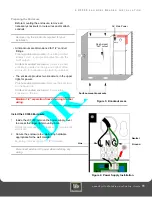
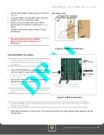
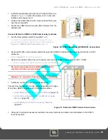
Install the appropriate wires into the AC terminal block,
as shown in
Figure 4
,
tighten the screws to 5 - 7 in-lbs., and
replace power supply cover.
Ensure all 120VAC wiring is confined within the power supply compartment when the cover is reinstalled to
maintain UL compliance.
5
Reconnect external AC power.
Maintain 1/4" separation from AC wiring to other wiring.
6
Connect to Network.
The LC3000 board provides both 10/100 Base-T TCP/IP and RS-485 network connections for communications
with the BbTS (NP, Network Processor). Select a connection based on the local network.
Once you connect the LC3000 to the network, configure the LC3000 for the network. Refer to the
(page 13) for details on configuring the unit.
LC3000 L
AUNDRY
R
EADER
C
ONFIGURATION
Configuration Methods
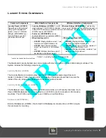
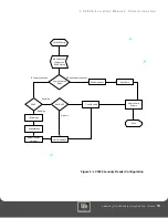
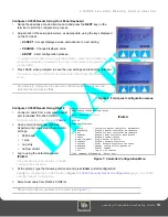
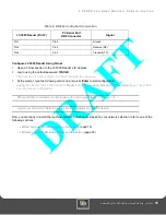
The Laundry Reader must be configured to interface with the BbTS network. Configure the Reader using either the
front panel of the Reader or the configuration port (see
Figure 5: LC3000 Laundry Reader Configuration
Future configuration modifications can be one using Telnet, if enabled.
Default Settings
The LC3000 Controller Unit default settings are:
• DHCP enabled
• NP (host) IP address assigned by DHCP server
Configure the LC3000 Laundry Reader to interface with BbTS, using one of three modes:
•
Front Panel Keyboard
•
Config Port -
provides for RS-232 connection to a computer with Hyperterminal software
•
Telnet
via IP if using Ethernet connections


