L E 3 / P S E N C L
A N D
L C M 2 0 I
N S T A L L A T I O N
Laundry Installation and Setup Guide
17
L E 3 / P S E N C L
A N D
L C M 2 0 I
N S T A L L A T I O N
3
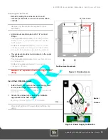
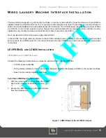
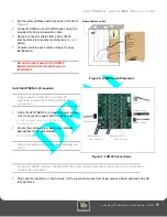
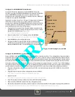
Set the rotary address switch to position 0. Refer to
Figure 8
.
4
Connect LCM20 to the LC3000 Reader, using the
provided RJ 45 communication cable.
5
Route 4-conductor cables from each LCM20
terminal block to a laundry machine (see
below).
6
Consider marking each cable uniquely for easy
identification.
Do not connect power to the LCM20
Board until all machine interfaces are
terminated.
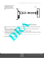
Figure 8: LCM20 Board Placement
Install LE3/PSENCL (if required)
If your Laundry Center has more than 20
machines, an external LCM20 and LE3/PSENCL
are required.
1
Inside the LE3/PSENCL, remove the power supply
cover to access the upper right mounting hole.
Protect power supply from debris while mounting
the enclosure.
2
Secure the enclosure to a wall using hardware
appropriate for the wall material.
Mounting holes accept up to 1/4” hardware.
Disconnect external AC power when installing any
wiring.
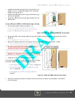
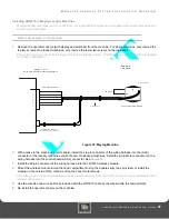
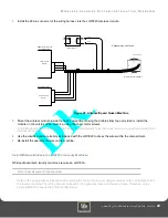
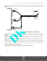
Figure 9: LCM20 Connections
Ensure all 120VAC wiring is confined within the power supply compartment when the cover is reinstalled to
maintain UL compliance.
3
Strip back the insulation on the AC wire .28" to prevent bare wire from being exposed when installed in the AC
terminal block.
power
TB1 to machine 1
TB4 to machine 4
TB3 to machine 3
TB2 to machine 2
TB5 to machine 5
LCM20 to LC3000
LCM20 to LCM20
ACMAIN
L N G
0 1
2
3
4
5
6
7
8
9
A
B
C
D
E
F
LINK/ACT
NET
100M
HOST RS-485
LCM20 RS-485
BRIDGE RS-485
AUX RS-485
Power
LWI
CONFIG
RS-232
CONFIG
Rotary address switch

