L E 3 / P S E N C L
A N D
L C M 2 0 I
N S T A L L A T I O N
Laundry Installation and Setup Guide
18
L E 3 / P S E N C L
A N D
L C M 2 0 I
N S T A L L A T I O N
4
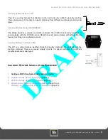
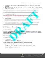
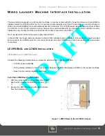
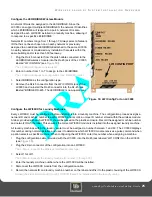
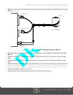
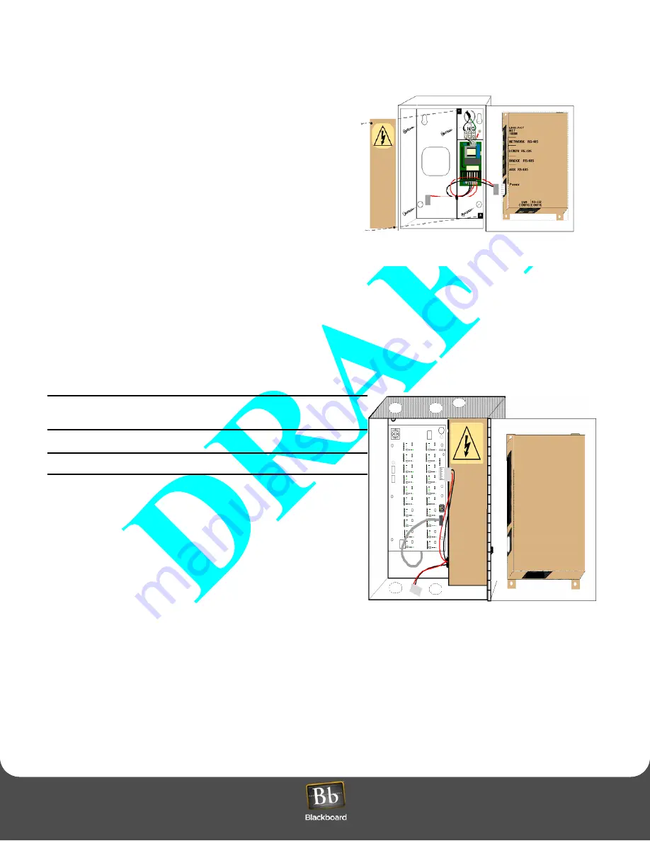
Install the appropriate wires into the AC terminal block, as
shown in
Figure 10
,
tighten the screws to 5-7 in-lbs.,and
replace power supply cover.
5
Position the LCM20 board, with component side facing out,
over the six standoffs.
6
Secure the LCM20 board using the #4-40 screws from the
hardware kit.
Connect External LCM20 to LC3000 and laundry machines
1
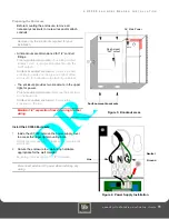
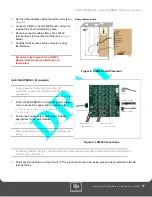
Set the rotary address switch to position 1 or 2.
Position 1 for machine numbers 21 through 40; and
position 2 for machine numbers 41 through 60. Refer to
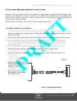
Figure 8: LCM20 Board Placement
Figure 10: LCM20 Board and LE3/PSENCL Connections
2
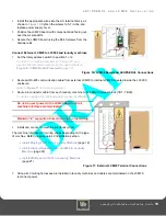
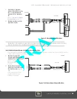
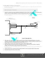
Route an RS-485 communication cable from external LCM20 to internal LCM20 mounted inside the LC3000
enclosure.
Refer to
3
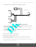
Route a 4-conductor cable from each laundry machine to an LCM20 terminal block (TB1 - TB20).
Consider marking each cable uniquely for easy identification.
Do not connect power to the LCM20 Board until all
machine interfaces are terminated.
Maintain 1/4" separation from AC wiring to other wiring.
4
Install and connect to machine interfaces (LCIs).
The machine interface (LCI) wiring varies depending on the type
of machine. Refer to appropriate LCI installation section:
•
Install Maytag LCI3010 in Laundry Machine
•
Install Alliance/Speed Queen LCI3020 in Laundry
Machine
•
Install Whirlpool LCI3030 in Laundry Machine
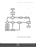
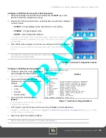
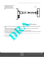
Figure 11: External LCM20 Terminal Connections
5
Once all LCI wiring harnesses are installed in laundry machines and cables are terminated on the LCM20,
reconnect power.


