background image

DRAFT

O

V E R V I E W

P

RINTED

 N

OVEMBER

 3, 2009                 


1-2

W

HAT

S


INCLUDED

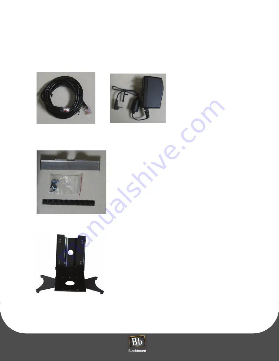
A hardware kit is provided with a security plate, rubber feet, and screws to aid in mounting the unit.

Figure 1-2 Cat-5 Cable and Power Supply

Figure 1-3 MF4100 Hardware Kit

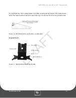
Figure 1-4 VESA Bracket

Cat-5 Cable

Wall Mount Power Supply

Security Plate

Screw kit

Rubber Feet

Summary of Contents for MF4100

Page 1: ...D R A F T MF4100 Installation Guide...

Page 2: ...erence caused by unauthorized modifications to this equipment Such modifications could void the user s authority to operate the equipment This equipment complies with the FCC radiation exposure limits...

Page 3: ...ons 3 Screw Positions 4 Assembly Details 5 Mount the MF4100 6 Wall Mount Installation 6 Attended Wall Mount Installation 8 Unattended Wall Mount Installation 10 Table Top Mount Installation 10 Table T...

Page 4: ...5 Figure 1 9 Table Top Mount Options 5 Figure 1 10 VESA Bracket Attended Wall Mount 6 Figure 1 11 MF4100 Cable Ports 7 Figure 1 12 Attended Wall Mount VESA Bracket Orientation 7 Figure 1 13 Reader Sec...

Page 5: ...tic stripe reader capabilities and can function as a Copy Reader Laundry Reader POS Terminal The MF4100 supports full video and audio playback allowing for a rich video experience for Advertising Aler...

Page 6: ...A hardware kit is provided with a security plate rubber feet and screws to aid in mounting the unit Figure 1 2 Cat 5 Cable and Power Supply Figure 1 3 MF4100 Hardware Kit Figure 1 4 VESA Bracket Cat...

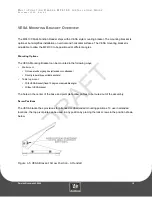
Page 7: ...gles Mounting Options The VESA Mounting Bracket can be mounted in the following ways Wall mount Onto an electrical gang box attended or unattended Directly to a wall use suitable anchors Table top mou...

Page 8: ...can be fixed by placing the lock screws in the position shown below This locked position conceals the cables from sight and secures them from being tampered with Figure 1 6 VESA Bracket Screw Positio...

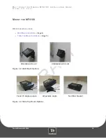
Page 9: ...9 5 R E V 0 1 PRINTED NOVEMBER 3 2009 1 5 MOUNT THE MF4100 MF4100 MOUNTING OPTIONS Wall Mount Installation Page 6 Table Top Mount Installation Page 10 Figure 1 8 Wall Mount Options Figure 1 9 Table T...

Page 10: ...by removing the 4 screws 1 8 Pin hex driver See VESA Bracket Assembly Details Page 4 3 Place the two locking screws in the position that allows the tilt plate to pivot 1 8 Pin hex driver See VESA Bra...

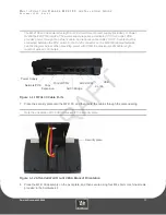
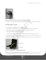
Page 11: ...switch to the RJ 45 connector on the MF4100 labeled Network see the diagram below When providing power with POE the maximum LAN cable length must not exceed 100 meters Figure 1 11 MF4100 Cable Ports 7...

Page 12: ...x to mount the MF4100 Ensure there is enough clearance for the operator to access the touchscreen and swipe cards 2 Remove the two base extensions by removing the 4 screws 1 8 pin hex driver See VESA...

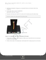
Page 13: ...e MF4100 See MF4100 Cable Ports Page 7 6 Place the security plate onto the MF4100 and then route the cables through the plate opening Note the orientation of the VESA bracket to the security plate Fig...

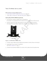
Page 14: ...re there is enough clearance for the operator to access the touchscreen and swipe cards 2 Install the rubber feet provided in the hardware kit to each corner of the base extensions The rubber feet are...

Page 15: ...n the unattended position See VESA Bracket Screw Position Unattended Page 4 For an adjustable angle install the MF4100 so the speaker opening is located near the hinge of the VESA mounting bracket Pla...

Page 16: ...er The rubber feet are self adhesive The bottom cover has round depressions in the plastic to locate the rubber feet Install a rubber foot at each of the four corners Figure 1 18 Reader Rubber Feet In...

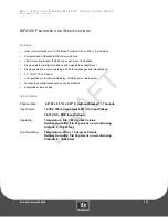
Page 17: ...ght level Displays balance account warnings and other messages after transactions 5 7 VGA TFT LCD panel Configuration via touchscreen display CONFIG port or web server Touchscreen configuration access...

Reviews: