background image

S E 3 - R D R 1 0 0  I

N S T A L L A T I O N 

G

U I D E

D

O C U M E N T 

1 2 9 1   

R

E V 

0 1

P

RINTED

 N

OVEMBER

 24, 2009                 

1-3

I

NSTALL THE 

SE3-RDR100

UL Considerations:

Attention to Installers: All field wiring/cabling connections made to the Controller need 
to use shielded cable with one of the shielded ends connected to earth ground.

Surface Mount the SE3-RDR100 

(page 1-3)

Single Gang Box Mount the SE3-RDR100 

(page 1-6)

The mounting plate is secured using #6 flat head hardware. Select hardware based on the mounting 

material.

To surface mount the SE3-RDR100

1

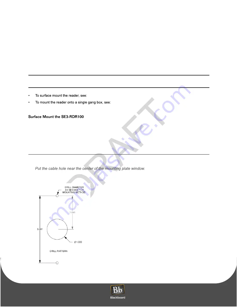
Use the mounting plate as a template to mark mounting holes and a cable routing hole.

2

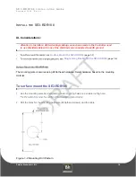
Drill the holes for the mounting hardware (#6 flathead screws) and the cable.

Figure 1-2 Mounting Drill Pattern

Summary of Contents for SE3-RDR100

Page 1: ......

Page 2: ...ntents PRINTED NOVEMBER 24 2009 I 2 SE3 RDR100 INSTALLATION GUIDE 3 Install the SE3 RDR100 3 Surface Mount the SE3 RDR100 6 Single Gang Box Mount the SE3 RDR100 9 Remove the SE3 RDR100 10 Specificatio...

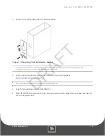
Page 3: ...late Installation Mullion 4 Figure 1 4 Mounting Plate Installation Surface Mount 5 Figure 1 5 Mullion Installation 5 Figure 1 6 Single Gang Box Mount Assembly 6 Figure 1 7 Mounting Plate Installation...

Page 4: ...onsible for any radio or TV interference caused by unauthorized modifications to this equipment This equipment complies with the FCC radiation exposure limits set forth for an uncontrolled environment...

Page 5: ...echnology Contactless Card Technology offers the following advantages vs magnetic stripe virtually eliminates reader wear and tear card need not contact the reader Figure 1 1 SE3 RDR100 Reader The SE3...

Page 6: ...h one of the shielded ends connected to earth ground Surface Mount the SE3 RDR100 page 1 3 Single Gang Box Mount the SE3 RDR100 page 1 6 The mounting plate is secured using 6 flat head hardware Select...

Page 7: ...ware Figure 1 3 Mounting Plate Installation Mullion 4 Pull the cable through the hole and then wire to the 5 pin terminal block SE3 RDR100 Wiring 5 Plug the terminal block onto the SE3 RDR100 6 Place...

Page 8: ...te Installation Surface Mount 7 Push the bottom of the reader onto the mounting plate to lock the unit to the plate Figure 1 5 Mullion Installation 8 Test the SE3 RDR100 for proper operation 9 Optiona...

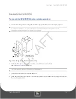
Page 9: ...appropriate hardware to the single gang box Figure 1 6 Single Gang Box Mount Assembly 2 Pull cable through mounting plate and then connect to 5 pin terminal block see SE3 RDR100 Wiring page 1 8 3 Plug...

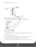
Page 10: ...te Installation Gang Box Mount 5 Push the bottom of the SE3 RDR100 onto the mounting plate to lock the unit to the plate Figure 1 8 Single Gang Box Mount 6 Test the reader for proper operation 7 Optio...

Page 11: ...I N S T A L L T H E S E 3 R D R 1 0 0 PRINTED NOVEMBER 24 2009 1 8 Figure 1 9 SE3 RDR100 Wiring Jumper wire between PINS 1 5...

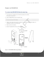
Page 12: ...talled remove the Security Screw Cover Decal 2 Insert the SE3 RDR100 key into the bottom slots 3 Gently pull the bottom of the reader at an angle over the mounting plate and then slide up to disengage...

Page 13: ...Celsius Relative Humidity 0 to 95 percent non condensing Altitude 0 10 000 feet Non Operating Temperature 20 to 70 degrees Celsius Relative Humidity 0 to 95 percent non condensing Altitude 0 35 000 f...

Reviews: