background image

B

L A C K B O A R D

  ( W R 5 0 0 0 )   R

E A D E R

  I

N S T A L L A T I O N

  G

U I D E

403-003-000 R

EV

 A


1-5

R

EADER

 I

NSTALLATION

 O

VERVIEW

When choosing a location to install the WR5000 reader, consider the following:

Proximity to entry point

Visibility and Access to Users

ADA Requirements

Protection of the reader from environmental elements

Cable distance/path:

1200 ft. maximum for RS-485 to Blackboard SA3032 

500 ft. maximum for Wiegand interface

500 ft. maximum for Wiegand interface

328 ft. maximum for Cat-5e cable

Reader Wiring

Based on the application of the reader, the wiring options are as follows:

Door Reader RS-485 Interface 

(page 1-5)

Door Reader Wiegand Interface 

(page 1-6)

Attendance Reader 

(page 1-7)

The hardware kit includes two (1 x 4) terminal blocks. These terminal blocks provide electrical connections 
to signals on the pin headers.

Two WR5000 readers can be connected to the Blackboard Access SA3032 to support ingress and egress 
configurations. The administrator must login to each reader and set the address. Verify that the readers do 
not have the same assigned address (0 or 1).

Note

: To maintain UL compliance, install only 1 wire in each terminal block opening. If 

necessary, use an external splice when more than one wire is required.

Install in accordance with the National Electrical Code (NEC), ANSI/NFPA 70, and local codes.

Door Reader RS-485 Interface

When using the RS-485 Interface option, only one terminal block is required. The connection points are 
shown in 

Table 1-2

. The TB1 designation is for the top four pins shown in 

Figure 1-3

.

Summary of Contents for WR5000

Page 1: ...403 003 000 Rev A Blackboard Wall Reader WR5000 Installation Guide...

Page 2: ...403 003 000 Rev A Table 1 Revision History Bb Document Part Number Rev Description Date 403 003 000 A ECO10418 Initial Release PENDING...

Page 3: ...ALLATION GUIDE 2 Federal Communications Commission FCC statement 4 Hardware Kit and Parts List 5 Reader Installation Overview 5 Reader Wiring 5 Door Reader RS 485 Interface 6 Door Reader Wiegand Inter...

Page 4: ...ts two modes of operation a door reader that interfaces to either the Blackboard Security Access System or third party control panels using a Wiegand interface A second mode of operation is as an atte...

Page 5: ...of this equipment in a residential area is likely to cause harmful interference in which case the user will be required to correct the interference at his own expense Modifications Any modifications m...

Page 6: ...Class A statement Attention This is a Class A product In a domestic environment this product may cause radio interference in which case the user may be required to take adequate measures Radiation Ex...

Page 7: ...gang box Figure 1 2 Hardware Kit Table 1 1 Hardware Parts List Item Description Use Qty 1 1 x 4m 3 5mm Terminal Block Attach wires to reader 2 2 M2 x 5 Button head Socket Cap Screw Secure Reader to mo...

Page 8: ...6 Attendance Reader page 1 7 The hardware kit includes two 1 x 4 terminal blocks These terminal blocks provide electrical connections to signals on the pin headers Two WR5000 readers can be connected...

Page 9: ...he reader to a Third party Controller using a Wiegand interface both terminal blocks are required Cable wiring should be a minimum of 24 AWG If a shielded cable shield is used ground the shield at the...

Page 10: ...d between the POE switch and the RJ 45 connector on the WR5000 cable length must not exceed 100 meters WARNING When using a POE switch to power the WR5000 both the POE switch and WR5000 must be instal...

Page 11: ...ication To mount the reader 1 Use the bracket marked OLD WORK when the gang box has tabs on the outside of the wall Use the bracket marked FLUSH MOUNT when the gang box is recessed or flush with wall...

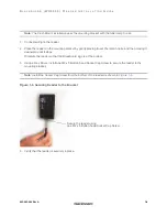
Page 12: ...over the ramp hooks and then moving it downward until it stops Orientate the reader so that the Blackboard logo is at the bottom 5 Using a Hex Driver install one M2 x 5 Button head Socket Cap Screw to...

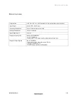
Page 13: ...max Operating Temperature 0 to 50 Celsius Indoor Use Only Storage Temperature 20 to 70 Celsius Inputs See Note 1 0 to 5 5V Wiegand Input Signals RLED GLED BEEPER 0 5 5V maximum Active when 2 5V driver...

Reviews: