background image

111-F00    Page 13/16 

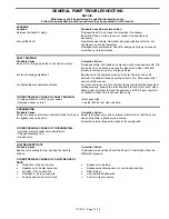
GENERAL PUMP TROUBLESHOOTING 


NOTICE: 

Maintenance shall be performed by qualified technicians only.   

Follow the appropriate procedures and warnings as presented in this manual. 


LEAKAGE 


Location 

Probable Cause/Corrective Action 

Between the head & casing 

Damaged head O-ring: Inspect and replace if necessary.  
Burrs/dirt in head O-ring groove or cylinder: File and clean as 
necessary. 


Around the shaft 

New Mechanical Seals: New seals may leak slightly at start up, but 
should seal up shortly thereafter. 
Damaged mechanical seals: Check for damaged O-rings or cracked, 
scratched or worn seal faces 


SHAFT BINDING 


Probable Cause 

Corrective Action 

Burrs, dirt or foreign particles on the heads or discs. 

During assembly, both heads and discs must be clean and smooth. File 
any burrs or rough spots, and wipe the discs with a clean cloth and 
alcohol to remove any dirt or foreign particles.  


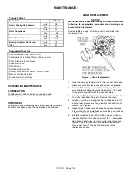
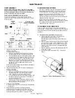
Improper bearing adjustment. 

Bearings must be adjusted properly to center the rotor and shaft 
between the head & bearing housing. Refer to the "Pump assembly " 
section of this manual. 


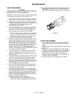
Contaminated mechanical seal faces. 

Any trace of grease or dirt on the seal faces will prevent the faces from 
mating properly, causing the rotor and shaft to bind or turn hard. Use a 
tissue paper & alcohol to clean the seal faces. NOTE: Apply a light oil 
or suitable lubricant to bronze seal faces only. 


OTHER POSSIBLE CAUSES OF SHAFT BINDING: 


• Foreign particles on rotor, liner or vanes. 
• Damaged vanes or rotor.  
 

• Bent push rods. 
• Liquids that "set up" when inactive. 


OVERHEATING 


Probable Cause 

Corrective Action 

Pump is in bypass (internal or external) mode too long or 
the bypass loop is too short 

Adjust the bypass valve and/or internal relief valve so that the pump 
does not operate in bypass mode so long. 

Route the external bypass line back to the supply tank. 


OTHER POSSIBLE CAUSES OF OVERHEATING: 


• Improper system bypass valve adjustment  
• Plugged discharge line. 
• Closed valve. 


LOW DELIVERY RATE 


Probable Cause 

Corrective Action 

Bypass valve setting too low, causing the liquid to 
bypass. 

The Bypass valve setting should be 20 psi (1.4 bar) higher than the 
differential pressure. 
 

OTHER POSSIBLE CAUSES OF A LOW DELIVERY 
RATE: 


Restriction in the suction line. 


Resistance in the discharge line. 


Air leaks in the suction line.  


Damaged or worn pump parts. 


Pump speed too low or too high. 


Bypass valve leaking.  


Bypass valve sticking open, or not properly seating. 

 Dirty 

strainer. 


Liner installed backwards 


Pump running in reverse 

Summary of Contents for 111-F01

Page 1: ...Service Numbers in parentheses following individual parts indicate reference numbers on Blackmer Part Lists SAFETY DATA This is a SAFETY ALERT SYMBOL When you see this symbol on the product or in the...

Page 2: ...ng pump service or maintenance can cause personal injury or property damage PUMP DATA PUMP IDENTIFICATION A pump Identification tag containing the pump serial number I D number and model designation i...

Page 3: ...nd installation of the piping system review the following suggestions 1 Locate the pump as near as possible to the source of supply to avoid excessive inlet pipe friction 2 The inlet line should be at...

Page 4: ...not available use a straight edge Turn both shafts by hand checking the reading through one complete revolution Maximum offset should be less than 005 127 mm 2 Angular alignment Insert a feeler gauge...

Page 5: ...alves are fully open and that the drain valves and other auxiliary valves are closed 4 Install inlet and discharge pressure gauges on the pump in the threaded connections provided These can be used to...

Page 6: ...tions OPTIONAL PUMP RELIEF VALVE Hazardous pressure can cause personal injury or property damage An external bypass valve and or an internal relief valve MUST be installed in the system to protect the...

Page 7: ...ace as required Reattach R V cap O ring and RV cap Refer to the individual Blackmer pump parts lists for various spring pressure ranges Unless specified otherwise pumps are supplied from the factory w...

Page 8: ...in this manual See the table on page 1 of this manual to determine what model you have Figure 6 Vane Replacement 1 Flush the pump per instructions in this manual Drain and relieve pressure from the p...

Page 9: ...pward and remove the 4 cap screws 21 Lift off the bearing housing and remove the cylinder O ring 71 7 The mechanical seal rotating assembly will come out with the shaft The stationary seat and station...

Page 10: ...e of bearing press the OD of the bearing into the bearing adjuster until fully seated 3 Cylinder O ring installation a Install a new O ring 71 over the dowel of the Bearing housing 57 4 Reassemble the...

Page 11: ...n the shaft end and the rotor c Install the seal spacer 82 over the shaft until it bottoms out on the large diameter of the shaft d Slide the seal rotating assembly 153B over the shaft with the rotati...

Page 12: ...housing Table 2 Pump size Distance on OD of Drive Housing PV S 6 8 3 4 19 05 mm 18 Tighten the bearing adjuster lock setscrews and torque per table 1 19 Install a new head O ring 72 on the dowel of th...

Page 13: ...the seal faces will prevent the faces from mating properly causing the rotor and shaft to bind or turn hard Use a tissue paper alcohol to clean the seal faces NOTE Apply a light oil or suitable lubric...

Page 14: ...use Air leaks in the suction line Restriction in the suction line Damaged or worn pump parts Too much lift for the vapor pressure of the fluid A dirty or clogged strainer Worn vanes Suction Valve Clos...

Page 15: ...111 F00 Page 15 16 NOTES...

Page 16: ...rine Magnetic Drive Pumps Stainless Steel 14 to 215 GPM Abaque Peristaltic Hose Pumps 0 1 to 210 GPM High Lift Solids Abrasives Reciprocating Gas Compressors Liquefied Gas Transfer Boosting Vapor Reco...

Reviews: