


111-F00 Page 2/16
SAFETY DATA
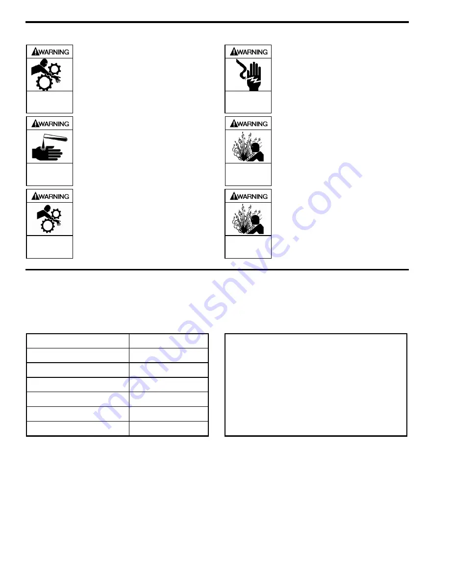
Hazardous
machinery can
cause serious
personal injury.
Failure to disconnect and lockout
electrical power or engine drive before
attempting maintenance can cause
severe personal injury or death
Hazardous voltage.
Can shock, burn or
cause death.
Failure to disconnect and lockout
electrical power before attempting
maintenance can cause shock, burns or
death
Hazardous or toxic
fluids can cause
serious injury.
If pumping hazardous or toxic fluids,
system must be flushed and
decontaminated, inside and out, prior to
performing service or maintenance
Hazardous pressure
can cause personal
injury or property
damage
Disconnecting fluid or pressure
containment components during pump
operation can cause serious personal
injury, death or major property damage
Do not operate
without guard
in place
Operation without guards in place can
cause serious personal injury, major
property damage, or death.
Hazardous pressure
can cause personal
injury or property
damage
Failure to relieve system pressure prior
to performing pump service or
maintenance can cause personal injury
or property damage.
PUMP DATA
PUMP IDENTIFICATION
A pump Identification tag, containing the pump serial number, I.D. number, and model designation, is attached to each pump. It is
recommended that the data from this tag be recorded and filed for future reference. If replacement parts are needed, or if
information pertaining to the pump is required, this data must be furnished to a Blackmer representative.
TECHNICAL DATA
INITIAL PUMP START UP INFORMATION
Pump Size
6, 8
Maximum Pump Speed
3600 RPM
Flow Rate at Max. Pump speed
6-8 GPM (23-30 LPM)
Maximum Operating Temperature
240°F (116°C)
Maximum Viscosity
5, 000 SSU (1100 cP)
Maximum Differential Pressure
125 psi (8.6 Bar)
Maximum Working Pressure
350 psi (24.1 Bar)
Model No.: ______________________________________
Serial No.: ______________________________________
ID No.: _________________________________________
Date of Installation: ______________________________
Inlet Gauge Reading: _____________________________
Discharge Gauge Reading: ________________________
Flow Rate: ______________________________________
Technical Data is for standard materials of construction.
Consult Blackmer Material Specs for optional materials of
construction
Summary of Contents for 111-F01
Page 15: ...111 F00 Page 15 16 NOTES...


