

111-F00 Page 4/16
INSTALLATION
PUMP MOUNTING
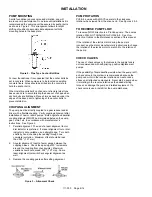
A solid foundation reduces noise and vibration, and will
improve pump performance. On permanent installations it is
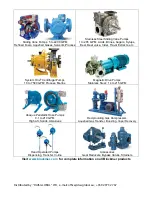
recommended the pumping unit be secured by anchor bolts
as shown in Figure 2. This arrangement allows for slight
shifting of position to accommodate alignment with the
mounting holes in the base plate.
Figure 2 - Pipe Type Anchor Bolt Box
For new foundations, it is suggested that the anchor bolts be
set in concrete. When pumps are to be located on existing
concrete floors, holes should be drilled into the concrete to
hold the anchor bolts.
When installing units built on channel or structural steel type
bases, use care to avoid twisting the base out of shape when
anchor bolts are tightened. Place shims as needed under the
edges of the base prior to tightening of the anchor bolts to
prevent distortion.
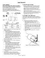
COUPLING ALIGNMENT
The pump must be directly coupled to a gear reducer and/or
driver with a flexible coupling. Verify coupling alignment after
installation of new or rebuilt pumps. Both angular and parallel
coupling alignment MUST be maintained between the pump,
gear, motor, etc. in accordance with manufacturer’s
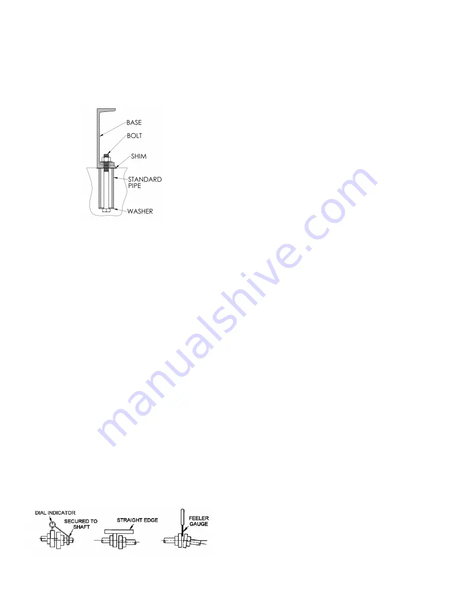
instructions. See Figure 3.
1. Parallel alignment: The use of a laser alignment tool or
dial indicator is preferred. If a laser alignment tool or dial
indicator is not available, use a straight edge. Turn both
shafts by hand, checking the reading through one
complete revolution. Maximum offset should be less
than .005" (.127 mm).
2. Angular alignment: Insert a feeler gauge between the
coupling halves. Check the spacing at 90° increments
around the coupling (four checkpoints). Maximum
variation should not exceed .005" (.127 mm). Some
laser alignment tools will check angular alignment as
well.
3. Replace the coupling guards after setting alignment.
Figure 3 – Alignment Check
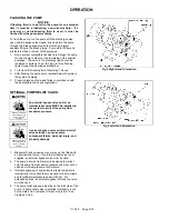
PUMP ROTATION
PV6 & 8 pumps will ALWAYS operate in the clockwise
rotation when viewed from the driven end. See Figures 4 & 5.
TO REVERSE PUMP FLOW
To reverse FLOW direction in a ProVane pump. The pumps
rotation WILL NOT CHANGE for PV(S)6 & 8. See
Flow
Direction Options
in the Maintenance section of this manual.
If the rotation of the electric motor driving the pump is
incorrect; see the motor manufacturer’s instructions to change
the rotation of the electric motor to match it to the rotation of
the pump.
CHECK VALVES
The use of check valves or foot valves in the supply tank is
not recommended with self-priming, positive displacement
pumps.
If the possibility of liquid backflow exists when the pump is off,
a check valve in the system is recommended because the
pump can motor in the reverse rotation and create undue
stress on all attached components. Never start a pump when
it is rotating in the reverse rotation as the added starting
torque can damage the pump and related equipment. If a
check valve is used, install it at the pump discharge.
Summary of Contents for 111-F01
Page 15: ...111 F00 Page 15 16 NOTES...