background image

111-F00     Page 5/16 

OPERATION 


Do not operate 

without guard 

in place 

Operation without guards in place can 
cause serious personal injury, major 
property damage, or death. 


Hazardous pressure 

can cause personal 

injury or property 

damage


Disconnecting fluid or pressure 
containment components during pump 
operation can cause serious personal 
injury, death or major property damage 


Hazardous pressure 

can cause personal 

injury or property 

damage 

Failure to relieve system pressure prior 
to performing pump service or 
maintenance can cause personal injury 
or property damage. 


Hazardous pressure 

can cause personal 

injury or property 

damage 

Pumps operating against a closed valve 
can cause system failure, personal 
injury and property damage  


Hazardous pressure 

can cause personal 

injury or property 

damage


An external bypass valve and/or internal 
relief valve must be installed in the 
system to protect the pump from 
excessive pressure.


Hazardous pressure 

can cause personal 

injury or property 

damage 

Incorrect bypass valve or internal relief 
valve settings can cause pump 
component failure, personal injury, and 
property damage. 


PRE-START UP CHECK LIST 

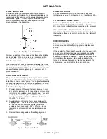
1.  Check the alignment of the pipes to the pump. Pipes 

must be supported so that they do not spring away or 
drop down when pump flanges or union joints are 
disconnected. 

2.  Verify proper coupling alignment. 

3.  Check the entire pumping system to verify that the proper 

inlet and discharge valves are fully open, and that the 
drain valves and other auxiliary valves are closed. 

4.  Install inlet and discharge pressure gauges on the pump 

in the threaded connections provided. These can be 
used to check actual suction and discharge conditions 
after pump start-up. 

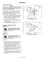
5.  Check the wiring of the motor, and briefly turn on the 

power to make sure that the pump rotates in the direction 
of the rotation arrow. 


START UP PROCEDURES 

NOTICE: 

Consult the "General Pump Troubleshooting" section of 
this manual if difficulties during start up are experienced. 


1.  Start the motor. Priming should occur within one minute. 

2.  Check the suction and discharge pressure gauges to see 

if the pump is operating within the expected conditions. 

3.  Check for leakage from the piping and equipment. 

4.  Check for overheating of the pump, reducer (if equipped), 

and motor. 

5.  If possible, check the flow rate. 

6.  Check the pressure setting of the system bypass valve 

by slowly restricting a valve in the discharge line and 
reading the pressure gauge. This pressure should be 20 
psi (1.4 bar) higher than the intended operating pressure.  


RUNNING THE PUMP IN REVERSE 

NOTICE: 

When pumps are operated in reverse a separate pressure 
relief valve must be installed to protect the pump from 
excessive pressure. 

NOTICE: 

Pump should be operated in reverse rotation for no more 
than 10 minutes and only when a separate pressure relief 
valve is installed to protect the pump from excessive 
pressure. 

 
It may be desirable to run the pump in reverse rotation for 
system maintenance.  The pump will operate satisfactorily in 
reverse rotation for a LIMITED time, 

at a reduced 

performance level. 

Summary of Contents for 111-F01

Page 1: ...Service Numbers in parentheses following individual parts indicate reference numbers on Blackmer Part Lists SAFETY DATA This is a SAFETY ALERT SYMBOL When you see this symbol on the product or in the...

Page 2: ...ng pump service or maintenance can cause personal injury or property damage PUMP DATA PUMP IDENTIFICATION A pump Identification tag containing the pump serial number I D number and model designation i...

Page 3: ...nd installation of the piping system review the following suggestions 1 Locate the pump as near as possible to the source of supply to avoid excessive inlet pipe friction 2 The inlet line should be at...

Page 4: ...not available use a straight edge Turn both shafts by hand checking the reading through one complete revolution Maximum offset should be less than 005 127 mm 2 Angular alignment Insert a feeler gauge...

Page 5: ...alves are fully open and that the drain valves and other auxiliary valves are closed 4 Install inlet and discharge pressure gauges on the pump in the threaded connections provided These can be used to...

Page 6: ...tions OPTIONAL PUMP RELIEF VALVE Hazardous pressure can cause personal injury or property damage An external bypass valve and or an internal relief valve MUST be installed in the system to protect the...

Page 7: ...ace as required Reattach R V cap O ring and RV cap Refer to the individual Blackmer pump parts lists for various spring pressure ranges Unless specified otherwise pumps are supplied from the factory w...

Page 8: ...in this manual See the table on page 1 of this manual to determine what model you have Figure 6 Vane Replacement 1 Flush the pump per instructions in this manual Drain and relieve pressure from the p...

Page 9: ...pward and remove the 4 cap screws 21 Lift off the bearing housing and remove the cylinder O ring 71 7 The mechanical seal rotating assembly will come out with the shaft The stationary seat and station...

Page 10: ...e of bearing press the OD of the bearing into the bearing adjuster until fully seated 3 Cylinder O ring installation a Install a new O ring 71 over the dowel of the Bearing housing 57 4 Reassemble the...

Page 11: ...n the shaft end and the rotor c Install the seal spacer 82 over the shaft until it bottoms out on the large diameter of the shaft d Slide the seal rotating assembly 153B over the shaft with the rotati...

Page 12: ...housing Table 2 Pump size Distance on OD of Drive Housing PV S 6 8 3 4 19 05 mm 18 Tighten the bearing adjuster lock setscrews and torque per table 1 19 Install a new head O ring 72 on the dowel of th...

Page 13: ...the seal faces will prevent the faces from mating properly causing the rotor and shaft to bind or turn hard Use a tissue paper alcohol to clean the seal faces NOTE Apply a light oil or suitable lubric...

Page 14: ...use Air leaks in the suction line Restriction in the suction line Damaged or worn pump parts Too much lift for the vapor pressure of the fluid A dirty or clogged strainer Worn vanes Suction Valve Clos...

Page 15: ...111 F00 Page 15 16 NOTES...

Page 16: ...rine Magnetic Drive Pumps Stainless Steel 14 to 215 GPM Abaque Peristaltic Hose Pumps 0 1 to 210 GPM High Lift Solids Abrasives Reciprocating Gas Compressors Liquefied Gas Transfer Boosting Vapor Reco...

Reviews: