111-F00 Page 6/16
OPERATION
FLUSHING THE PUMP
NOTICE:
If flushing fluid is to be left in the pump for an extended
time, it must be a lubricating, non-corrosive fluid. If a
corrosive or non-lubricating fluid is used, it must be
flushed from the pump immediately.
To flush the pump, run the pump with the discharge valve
open and the intake valve closed. Bleed air into the pump
through the intake gauge plug hole or through a larger
auxiliary fitting in the intake piping. Pump air for 30 second
intervals to clean out most of the pumpage.
1. Run a system compatible flushing fluid through the pump
for one minute to clear out the remainder of the original
pumpage. The valve in the discharge line should be
restricted to build up 10 psi (0.7 bar) to force flushing
liquid through the bearing seal chamber.
2. To remove the flushing fluid, follow step 1 above.
3. After flushing the pump some residual fluid will remain in
the pump and piping.
4. Properly dispose of all waste fluids in accordance with
the appropriate codes and regulations.
OPTIONAL PUMP RELIEF VALVE:
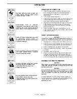
Hazardous pressure
can cause personal
injury or property
damage
An external bypass valve and/or an
internal relief valve MUST be installed in
the system to protect the pump from
excessive pressure.
Hazardous pressure
can cause personal
injury or property
damage
.
Incorrect bypass valve or internal relief
valve settings can cause pump
component failure, personal injury, and
property damage.
1. Blackmer ProVane pumps may or may not be fitted with
an internal relief valve. If an internal relief valve is not
supplied, an external bypass valve must be used.
2. The pump’s internal relief valve is designed to protect
only the pump from excessive pressure and must not be
used as a system pressure control valve.
3. Internal bypassing of liquid elevates liquid temperature.
Internal relief valve should only be used for brief periods
and for differential pressures below 125 psi. For
extended periods, an external bypass returned to source
must be used.
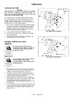
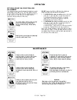
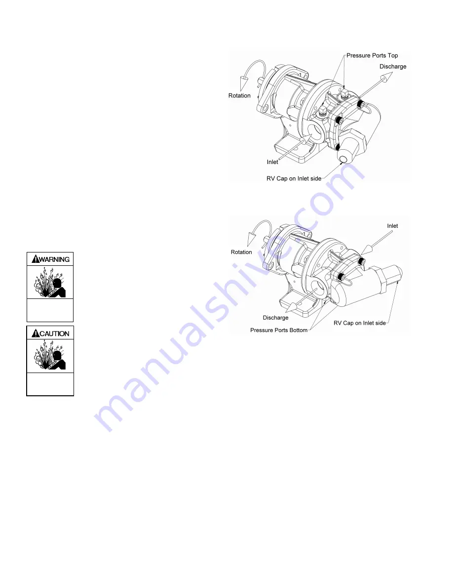
4. The pump relief valve cap must be on the inlet side of the
pump. If pump relief valve is installed improperly, it will
not operate and a component failure may result. See
Figures 4 and 5.
Fig 4 Right Hand Orientation
Fig 5 Left Hand Orientation
Summary of Contents for 111-F01
Page 15: ...111 F00 Page 15 16 NOTES...


