

111-F00 Page 9/16
MAINTENANCE:
PUMP DISASSEMBLY
NOTICE:
Follow all hazard warnings and instructions provided in
the “Maintenance” section of this manual.
NOTE:
The numbers in parentheses following individual parts
indicate reference numbers on the Pump Parts List.
1. Flush the pump per instructions in this manual. Drain and
relieve pressure from the pump and system as required.
2. Starting on the inboard (driven) end of the pump, clean
the pump shaft thoroughly, making sure the shaft is free of
nicks and burrs. This will prevent damage to the
mechanical seal when removed.
3. Remove the head cap screws (21). Gently pry the head
away from the casing using two large screwdrivers. The
head O-ring should come off with the head assembly.
4. Remove locknut and lock washer (24A and 24B):
a. Bend up the engaged lock washer tang and rotate the
locknut counterclockwise to remove it from the shaft.
b. Slide the lock washer off the shaft. Inspect the lock
washer for damage and replace as required.
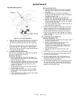
5. Remove the rotor and shaft (13) from the casing. While
one hand is pushing the shaft, the other hand should be
cupped underneath the rotor to prevent the vanes (14)
and pushrods (77) from falling out. As the rotor & shaft
are removed further, carefully support the shaft so it does
not drop and damage the sleeve bearing or finished
surfaces of the shaft or the rotating seal face as it is
removed. Carefully set the rotor and shaft aside for future
vane replacement and reassembly.
6. To remove the cylinder. Lay the pump on end with the
bearing housing facing upward and remove the 4 cap
screws (21). Lift off the bearing housing and remove the
cylinder O-ring (71).
7. The mechanical seal rotating assembly will come out with
the shaft. The stationary seat and stationary seal ring
need to be removed from the bearing adjuster (188).
8. Carefully pry the stationary seal elements (153A) from the
bearing adjuster (188). Be sure not to scratch the seal
face or damage the elastomer seal seat.
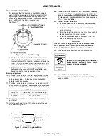
9. Remove the ball bearing adjuster (188) by loosening the
set screws (189) and turning it counter clockwise with a
strap wrench or spanner wrench.
10. If necessary for replacement, remove the ball bearing
(24C) from the bearing adjuster. Turn the bearing adjuster
so the threaded side is up. Using an appropriately sized
arbor press remove the bearing (24C) from the bearing
adjuster. Discard old bearing and replace with new one.
See step 2 of “PUMP ASSEMBLY”
11. If the sleeve bearing is worn or damaged.
a. Remove the sleeve bearing (24) from the bearing
housing (57) using an appropriately sized arbor press.
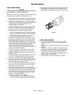
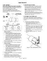
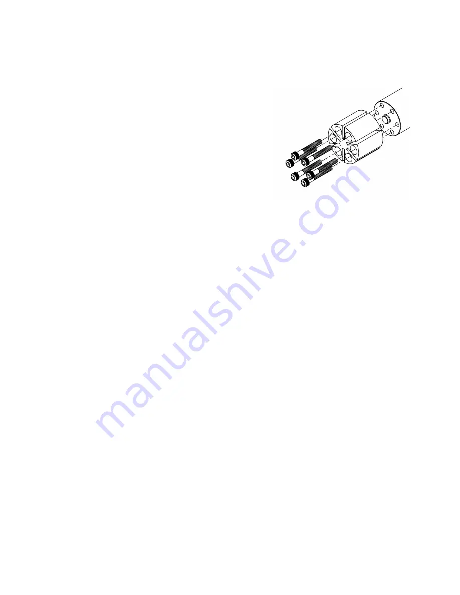
12.
Only disassemble rotor & shaft if necessary for part
replacement
. Disassemble the rotor (13B) and shaft
(13A) by removing the six cap-screws (13C). See figure
7.
Figure 7
PARTS REPLACEMENT
1. If any of the O-rings have been removed or disturbed
during disassembly, they need to be replaced with new
O-rings.
NOTE:
PTFE O-rings should be heated in hot water to aid
installation.
2. Excessive or continuous leakage from around the seal
housing or in the bearing housing may be an indication of
a damaged mechanical seal. If a mechanical seal has
been leaking, it is recommended the entire seal be
replaced. Refer to "General Pump Troubleshooting" for
possible causes of seal leakage.
3. Inspect bearings for wear and replace as necessary.
Summary of Contents for 111-F01
Page 15: ...111 F00 Page 15 16 NOTES...


