background image

701-B00    page 2/12 

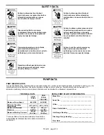
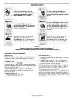
SAFETY DATA 


Hazardous 

machinery can 

cause serious 

personal injury.


Failure to disconnect and lockout 
electrical power or engine drive before 
attempting maintenance can cause 
severe personal injury or death 


Hazardous voltage. 

Can shock, burn or 

cause death.


Failure to disconnect and lockout 
electrical power before attempting 
maintenance can cause shock, burns or 
death 


Hazardous pressure 

can cause serious 

personal injury or 

property damage 

Disconnecting fluid or pressure 
containment components during pump 
operation can cause serious personal 
injury or property damage.


Hazardous pressure 

can cause serious 

personal injury or 

property damage


Failure to relieve system pressure prior 
to performing pump service can cause 
serious personal injury or property 
damage.


Systems with meters will still 

be pressurized even after the hose is 
emptied


Hazardous or toxic 

fluids can cause 

serious injury. 

If pumping hazardous or toxic fluids, 
system must be flushed and 
decontaminated, inside and out, prior to 
performing service or maintenance 


Hazardous 

machinery can cause 

severe personal 

injury or property 

damage.

Failure to set the vehicle emergency 
brake and chock wheels before 
performing service can cause severe 
personal injury or property damage.


Do not operate 

without guard  

in place


Operation without guards in place can 
cause serious personal injury, major 
property damage, or death. 


PUMP DATA 

 
PUMP IDENTIFICATION 

A pump Identification tag, containing the pump serial number, I.D. number, and model designation, is attached to each pump.  It is 
recommended that the data from this tag be recorded and filed for future reference. If replacement parts are needed, or if 
information pertaining to the pump is required, this data must be furnished to a Blackmer representative. 


TECHNICAL DATA 


CRL2 

TCRL2 

CRL3 

TCRL3 

CRL3-OE1 

Maximum Pump Speed 

640 RPM 

640 RPM 

Minimum Operating 
Temperature 

-30°F (-34°C) 

-30°F (-34°C) 

Maximum Differential 
Pressure 

100 psi 

(6.9 Bar) 

100 psi 

(6.9 Bar)

Maximum Working Pressure 

525 psi 

(36.2 Bar) 

525 psi 

(36.2 Bar)

 
* Technical Data is for standard materials of construction.  
Consult Blackmer Material Specs for optional materials of 
construction. 

INITIAL PUMP START UP INFORMATION 

Model No.: ____________________________________ 

Serial No.:  ____________________________________ 

ID No.:  _______________________________________ 

Date of Installation: _____________________________ 

Inlet Gauge Reading: ____________________________ 

Discharge Gauge Reading: _______________________ 

Flow Rate: _____________________________________ 


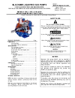
Summary of Contents for CRL2

Page 1: ...mer Service SAFETY DATA This is a SAFETY ALERT SYMBOL When you see this symbol on the product or in the manual look for one of the following signal words and be alert to the potential for personal inj...

Page 2: ...nd chock wheels before performing service can cause severe personal injury or property damage Do not operate without guard in place Operation without guards in place can cause serious personal injury...

Page 3: ...tions 1 Locate the pump as near as possible to the source of supply to avoid excessive inlet pipe friction 2 The inlet line should be at least as large as the intake port on the pump It should slope d...

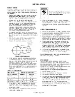
Page 4: ...odate alignment with the mounting holes in the base plate For new foundations it is suggested that the anchor bolts be set in concrete When pumps are to be located on existing concrete floors holes sh...

Page 5: ...82 and the belt guard brace 182A to the unit base 32 Do not operate without guard in place Operation without guards in place can cause serious personal injury major property damage or death 9 Check th...

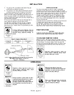
Page 6: ...cation every three months at minimum Refer to the Lubrication section of this manual Hydraulically driven units MUST contain speed control devices to prevent pump speeds above the maximum RPM specific...

Page 7: ...3 1 0 bar less than the external bypass valve setting Pump speeds which result in higher pressures nearing the valve setting forces the liquid to recirculate creating excessive wear on the pump and eq...

Page 8: ...ice can cause severe personal injury or property damage NOTICE Maintenance shall be performed by qualified technicians only Following the appropriate procedures and warnings as presented in this manua...

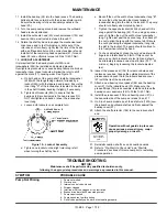
Page 9: ...and replace as required c Repeat steps a and b on the opposite shaft end 6 Remove the head capscrews 21 and carefully pry the head 20 away from the casing 12 7 Slide the head 20 off the shaft The hea...

Page 10: ...to the rotor slots with the rounded edges outward and the vane relief grooves facing TOWARDS the direction of rotation See Figure 10 c After the bottom vanes and push rods are installed insert the rot...

Page 11: ...24 Then using a spanner wrench tighten the nut the width of one lockwasher tang Tighten just past the desired tang then back off the nut to align the tang with the locknut slot Secure the nut by bendi...

Page 12: ...erly anchored piping 8 Bent shaft or drive coupling misaligned 9 Excessively worn rotor 10 Malfunctioning valve in the system 11 Relief valve setting too low 12 Liner installed backwards 13 Damaged va...

Reviews: