MAINTENANCE
11
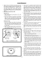
Figure 10 - Locknut Adjustment
13.
LOCKNUT ADJUSTMENT
It is important that the bearing locknuts (24A) and
lockwashers (24B) be installed and adjusted properly.
Overtightening locknuts can cause bearing (24) failure or a
broken lockwasher tang. Loose locknuts will allow the rotor
to shift against the discs (71), causing wear. See Figure 10.
a. On both ends of the pump shaft, install a lockwasher
(24B) with the tangs facing outward, followed by a
locknut (24A) with the tapered end inward. Ensure the
inner tang "A" of the lockwasher is located in the slot in
the shaft threads, bending it slightly, if necessary.
b. Tighten both locknuts (24A) to ensure that the bearings
(24) are bottomed in the head recess. DO NOT over-
tighten and bend or shear the lockwasher inner tang.
c. Loosen both locknuts (24A) one complete turn.
d. Tighten one locknut (24A) until a slight rotor drag is felt
when turning the shaft by hand.
e. Back off the locknut (24A) the width of one lockwasher
tang "B". Secure the locknut by bending the closest
aligned lockwasher tang into the slot in the locknut. The
pump must turn freely when rotated by hand.
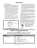
OPERATION WITHOUT GUARDS IN
PLACE CAN CAUSE SERIOUS
PERSONAL INJURY, PROPERTY
DAMAGE, OR DEATH.
Do not operate
without guard
in place.
f. Tighten the opposite locknut (24A) by hand until it is
snug against the bearing (24). Then, using a spanner
wrench, tighten the nut the width of one lockwasher
tang. Tighten just past the desired tang, then back off
the nut to align the tang with the locknut slot. Secure
the nut by bending the aligned lockwasher tang into the
slot in the locknut. The pump must continue to turn
freely when rotated by hand.
g. To check adjustment, grasp the locknut (24A) and
lockcollar (24B) with fingers and rotate back and forth.
If this cannot be done, one or both locknuts are too tight
and must be alternately loosened one stop at a time
(.001" - 25 microns). Begin by loosening the locknut
adjusted last.
14. Inspect the grease seal (104) for wear or damage and
replace as required. Grease the outside diameter of the
grease seal and push it into the inboard bearing cover (27)
with the lip of the seal inward.
15. Attach a new bearing cover gasket (26) and the bearing
cover (27) to the inboard head (20). Make sure the grease
fittings (76) are accessible. Install and torque the bearing
cover capscrews (28) to 30 lbs ft (47 Nm).
16. Install the grease seal (104) in the outboard bearing cover
(27) as instructed in step 14.
17. Attach a new bearing cover gasket (26) and the outboard
bearing cover (27) to the outboard head (20). Make sure
the grease fittings (76) are accessible. Install and torque
the bearing cover capscrews (28) to 30 lbs ft (47 Nm).
18. Attach the shaft protector (186) to the non-driven shaft end.
GENERAL PUMP TROUBLESHOOTING
NOTICE:
MAINTENANCE SHALL BE PERFORMED BY QUALIFIED TECHNICIANS ONLY, FOLLOWING
THE APPROPRIATE PROCEDURES AND WARNINGS AS PRESENTED IN THIS MANUAL.
SYMPTOM
PROBABLE CAUSE
Pump Not Priming
1. Pump not wetted.
2. Worn vanes.
3. Internal control or inlet valve closed.
4. Strainer clogged.
5. Inlet line or valves clogged or too restrictive.
6. Broken drive train (truck mounted pumps).
7. Pump vapor-locked.
8. Pump speed too low for priming.
9. Relief valve partially open, worn or not seating properly.
Pump Troubleshooting continued on back page.


