102-A00 page 11/16
MAINTENANCE
COMPLETE PUMP ASSEMBLY
Before reassembling the pump, inspect all component
parts for wear or damage, and replace as required. Wash
out the bearing/seal recess of the head and remove any
burrs or nicks from the rotor and shaft. Remove any
burrs from the liner.
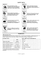
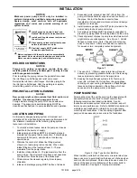
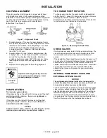
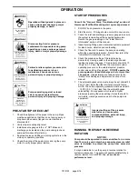
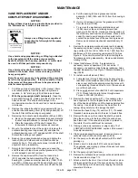
NOTICE:
Use a hoist and eyebolts installed in the threaded holes
located in the heads, discs, rotor and casing to lift the
heavy pump parts.
Always use a lifting device capable of
supporting the full weight of the pump
assemblies.
Heavy assemblies can
cause personal injury
or porperty damage.
1. Set the pump casing upright (feet down).
2. The liner must be installed in the pump casing with the
word “INTAKE” cast on the liner toward the intake port of
the pump casing.
Align the keyway in the top of the liner with the pin in the
top of the casing.
Uniformly tap the outer edge of the liner with a rubber
mallet to fully insert into the casing.
3.
Start assembly on the
OUTBOARD
non-driven side of
the pump:
For a CLOCKWISE rotation pump, the INTAKE port is to
the
left
.
For a COUNTERCLOCKWISE rotation pump, the
INTAKE port is to the
right
.
Loosely assemble the outboard disc (71) and head (20)
to the casing (12). The bearing, seal, O-rings, etc. will be
installed later.
4. Set the pump on its side with the outboard head DOWN.
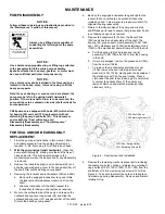
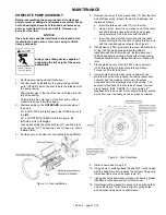
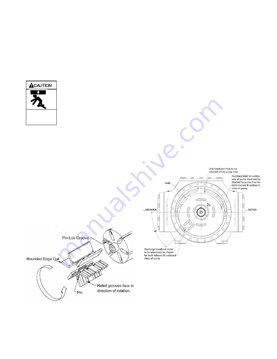
Figure 5 – Vane Installation
5. Remove the vanes (14) and push rods (77) from the rotor
and shaft assembly. Inspect for wear and damage, and
replace as follows:
a. Insert the three push rods (77) into the rotor.
b. Using a hoist, lower the non-driven end of the rotor
and shaft into the open side of the pump casing,
being careful not to hit the disc with the shaft.
c.
Insert the vanes into the rotor slots with the relief
grooves facing in the direction of pump rotation, and
with the rounded edges outward. See Figure 5.
6. If shaft sleeve (154A) previously removed, lubricate inner
O-ring (154B) using bearing grease identified in
lubrication section of this manual. Install sleeve over
shaft while aligning mounting holes with corresponding
threaded holes in rotor. Sleeve should mount flush with
rotor
7. Place small amount of Loctite # 220 onto capscrews
(155), thread fully into rotor holes through sleeve.
Torque to 200 inlbf (22.6 Nm).
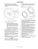
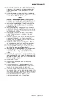
8. Using a hoist, install the disc in the casing with the
smooth side of the disc towards the casing (seal cavity
outward) and the pressure relief hole 45 degrees
downward from the discharge side of the casing. The
seal cavity feedback hole should be exposed into inlet
area of pump. (SEE FIGURE 9). There exists a 2
nd
feedback hole in each disc which should be fully covered
by the liner near the seal point when properly oriented.
Figure 9 – Disc Orientation
9. Install a new head O-ring (72).
10. Using a hoist, carefully attach the head (20) to the casing
with the head drain hole towards the bottom of the pump.
Install and tighten the head capscrews (21).
11. Lightly lubricate shaft sleeve surface with bearing grease
identified in lubrication section of this manual.
12. Install seal rotating assembly minus carbon rotating face
onto shaft sleeve. Take care to align mounting holes
with corresponding holes on shaft sleeve.


