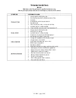
background image

701-D00     page 15/16


TROUBLESHOOTING 

NOTICE: 

Maintenance shall be performed by qualified technicians only,  

following the appropriate procedures and warnings as presented in this manual. 


SYMPTOM PROBABLE 

CAUSE 

Damaged Vanes 

1.  Foreign objects entering the pump. 

2.  Running the pump dry for extended periods of time. 

3. Cavitation. 

4.  Incompatibility with the liquids pumped. 

5. Excessive 

heat. 

6.  Worn or bent push rods, or worn push rod holes. 

7.  Hydraulic hammer - pressure spikes. 

8.   Vanes installed incorrectly (see"Vane Replacement"). 

Broken Shaft 

1.  Foreign objects entering the pump. 

2.  Relief valve not opening. 

3.  Hydraulic hammer - pressure spikes. 

4.  Pump/driver, driveline/drive shaft misalignment. 

5.  Excessively worn vanes or vane slots. 

SEAL LEAKAGE 

1.  O-rings not compatible with the liquids pumped. 

2.  O-rings nicked, cut or twisted. 

3.  Shaft at seal area damaged, worn or dirty. 

4.  Ball bearings overgreased. 

5. Excessive 

cavitation. 

6.  Mechanical seal faces cracked, scratched, pitted or dirty. 

MOTOR OVERLOAD 

1. 

Horsepower of motor not sufficient for application 

2. 

Improper wire size / wiring and/or voltage to motor. 

3. 

Misalignment in pump drive system. 

4. 

Excessive viscosity, pressure or speed. 

5. 

Bearing locknuts adjusted improperly. 

6. 

Faulty or worn bearings. 

7. 

Rotor rubbing against head or cylinder. 

8. 

Dirty mechanical seal faces. 


Summary of Contents for CRL8A

Page 1: ...his is a SAFETY ALERT SYMBOL When you see this symbol on the product or in the manual look for one of the following signal words and be alert to the potential for personal injury death or major proper...

Page 2: ...eight of the pump assemblies Failure to set the vehicle emergency brake and chock wheels before performing service can cause severe personal injury or property damage Heavy assemblies can cause person...

Page 3: ...e located at least 5 10 pipe diameters from the pump intake 4 Install an intake strainer 5 10 pipe diameters from the pump intake The strainer should have a net open area of at least four times the ar...

Page 4: ...COUNTERCLOCKWISE rotation NOTICE Confirm correct pump rotation by checking the pump rotation arrows respective to pump driver rotation TO CHANGE PUMP ROTATION To change pump rotation the pump must be...

Page 5: ...ng within expected parameters Record the gauge readings in the Initial Start Up Information section of this manual 4 Inspect piping fittings and associated system equipment for leaks noise vibration a...

Page 6: ...pressure relief valve can cause pump component failure personal injury and property damage Hazardous pressure can cause personal injury or property damage Relief valve cap is exposed to pumpage and w...

Page 7: ...CRL8 178 lbs ft 241 Nm 50 lbs ft 68 Nm 50 lbs ft 68 Nm SCHEDULED MAINTENANCE STRAINERS Strainers must be cleaned regularly to avoid pump starvation Schedule will depend upon the application and condi...

Page 8: ...a Bend up the engaged lockwasher tang and rotate the locknut counterclockwise to remove it from the shaft b Slide the lockwasher off the shaft Inspect the lockwasher for damage and replace as require...

Page 9: ...ubsequent product leakage 16 Install carbon rotating face 153F and O ring 153L over shaft sleeve 154A while aligning drive notches in carbon with drive pins in seal rotating assembly see figure 8 Figu...

Page 10: ...4C from the housing in the hub b If worn or damaged remove the grease seal 104A from the carrier 104B c To remove the mechanical seal stationary seat 153B remove the seal retaining screws and washers...

Page 11: ...e three push rods 77 into the rotor b Using a hoist lower the non driven end of the rotor and shaft into the open side of the pump casing being careful not to hit the disc with the shaft c Insert the...

Page 12: ...he bearing Place the grease seal carrier 104B with new O ring 104C into the hub 20C 19 Hand pack the ball bearing 24 with grease Refer to the Lubrication section for the recommended grease 20 Install...

Page 13: ...ang into the slot in the locknut The pump should continue to turn freely when rotated by hand 29 Inspect the grease seal 104 for wear or damage and replace as required Grease the outside diameter of t...

Page 14: ...Damaged or worn parts vanes discs liner or rotor 5 Excessive restriction in discharge line causing partial flow through the relief valve 6 Relief Valve worn set too low or not seating properly 7 Exte...

Page 15: ...ntering the pump 2 Relief valve not opening 3 Hydraulic hammer pressure spikes 4 Pump driver driveline drive shaft misalignment 5 Excessively worn vanes or vane slots SEAL LEAKAGE 1 O rings not compat...

Page 16: ...701 D00 page 16 16 1809 Century Avenue Grand Rapids Michigan 49503 1530 U S A Telephone 616 241 1611 Fax 616 241 3752...

Reviews: