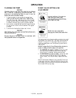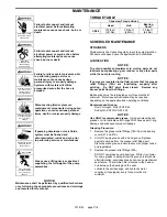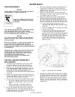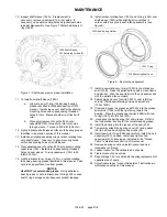
701-D00 page 4/16
INSTALLATION
COUPLING ALIGNMENT
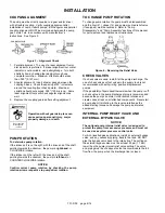
The pump must be directly coupled to a gear and/or driver
with a flexible coupling. Verify coupling alignment after
installation of new or rebuilt pumps. Both angular and parallel
coupling alignment MUST be maintained between the pump,
gear, motor, etc. in accordance with manufacturer’s
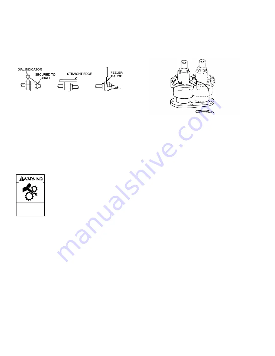
instructions. See Figure 3.
Figure 3 – Alignment Check
1. Parallel alignment: The use of a laser alignment tool or
dial indicator is preferred. If a laser alignment tool or dial
indicator is not available, use a straightedge. Turn both
shafts by hand, checking the reading through one
complete revolution. Maximum offset should be less
than .005" (0.127 mm).
2. Angular alignment: Insert a feeler gauge between the
coupling halves. Check the spacing at 90° increments
around the coupling (four check points). Maximum
variation should not exceed .005" (125 microns). Some
laser alignment tools will check angular alignment as
well.
3. Replace the coupling guards after setting alignment.
Operation without guards in place can
cause serious personal injury, major
property damage, or death.
Do not operate
without guard
in place
PUMP ROTATION
To determine pump rotation:
If the intake port is on the right, with the drive end of the shaft
pointing towards the observer, the pump is
right-hand
, or
CLOCKWISE rotation.
If the intake is on the left, with the drive end of the shaft
pointing towards the observer, the pump is
left-hand
, or
COUNTERCLOCKWISE rotation.
NOTICE:
Confirm correct pump rotation by checking the pump
rotation arrows respective to pump driver rotation.
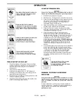
TO CHANGE PUMP ROTATION
To change pump rotation the pump must be disassembled
and the liner (41), vanes (14) and pump mounted relief valve
(if equipped) must be reversed. Refer to “Pump
Disassembly” and “Pump Assembly” sections of this manual
for parts removal and replacement instructions.
Figure 4 – Reversing the Relief Valve
CHECK VALVES
If a check valve is used, install it at the pump discharge. The
use of check valves or foot valves in the supply tank is not
recommended with self-priming, positive displacement
pumps.
If the possibility of liquid backflow exists when the pump is off,
a check valve in the pump discharge piping is recommended
because the pump can motor in the reverse rotation and
create undue stress on all attached components. Never start
a pump when it is rotating in the reverse rotation as the
added starting torque can damage the pump and related
equipment.
INTERNAL PUMP RELIEF VALVE AND
EXTERNAL BYPASS VALVE
NOTICE:
The optional pump internal relief valve is designed to
protect the pump from excessive pressure and must not
be used as a system pressure control valve.
For ALL liquefied gas applications, install an external bypass
valve, and any necessary piping, back to the tank. DO NOT
pipe the bypass valve back to the intake line. The setting on
the external bypass valve must be at least 25 psi (1.7 bar)
lower than the pump internal relief valve setting. The valve
and piping must be of adequate size to accommodate the full
flow from the pump when the discharge line is closed.


