701-D00 page 8/16
MAINTENANCE
PUMP DISASSEMBLY
NOTICE:
Follow all hazard warnings and instructions provided in
the “Maintenance” section of this manual.
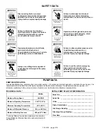
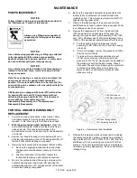
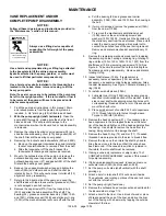
Always use a lifting device capable of
supporting the full weight of the pump
assemblies.
Heavy assemblies can
cause personal injury
or porperty damage.
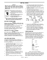
NOTICE:
Use a hoist and appropriate sling or lifting lugs attached
to the baseplate to lift the entire pump assembly.
Eyebolts attached to the pump, gearbox, or motor must
be used to lift that particular component only.
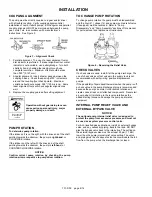
NOTICE:
Use a hoist and eyebolts installed in the threaded holes
located in the heads, discs, rotor and casing to lift the
heavy pump parts.
Note: If a seal, bearings or vanes are to be replaced, the
pump may be left in the upright (shaft horizontal)
position. If the rotor-shaft or liner is to be removed, the
pump will have to be placed on its side (shaft vertical) for
some operations.
CRL8 pumps are equipped with hubs (20C) which allow
for bearing (24) and seal (153) replacement without
disturbing the pump head bolts (21). This document
covers both the “Seal or Bearing only”
Disassembly/Reassembly and “Complete pump”
Disassembly/Reassembly
FOR SEAL AND/OR BEARING ONLY
REPLACEMENT
1. Flush the pump per instructions in this manual. Drain
and relieve pressure from the pump and system as
required. A 3/4" drain plug (29) is fitted in each head.
2.
With the pump upright (shaft horizontal).
Clean the
pump shaft thoroughly, making sure the shaft is free of
nicks and burrs. This will prevent damage to the
mechanical seal when the inboard hub or head assembly
is removed.
3. Remove the inboard bearing cover capscrews (28) and
slide the inboard bearing cover (27A) and gasket (26) off
the shaft. Discard the bearing cover gasket.
4. Removing the locknuts and lockwashers (24A and 24B):
a. Bend up the engaged lockwasher tang and rotate
the locknut counterclockwise to remove it from the
shaft
b. Slide the lockwasher off the shaft. Inspect the
lockwasher for damage and replace as required.
5. Move to the outboard side of the pump and remove the
outboard bearing cover capscrews (28) and slide the
outboard bearing cover (27) and gasket (26) off the shaft.
Discard the bearing cover gasket.
6. Bend up the engaged lockwasher tang and tighten the
locknut (24A) on outboard end until shaft cannot be
rotated by hand. This will ensure proper rotor/shaft (13)
alignment during reassembly.
7. Return to the inboard side of the pump and wrap the
shaft threads with tape to ensure that grease seal (104A)
is not damaged upon hub removal.
8. Remove the capscrews (21A) from the inboard hub
(20C) and slide the hub assembly off the shaft. The
bearing (24), grease seal carrier assembly (104B, 104A
and 104C), stationary seat (153B) and stationary O-ring
(153D) of the mechanical seal will come off with the hub.
a. Pull the bearing (24) and grease seal carrier
assembly (104B, 104A and 104C) from the housing
in the hub.
b. If worn or damaged, remove the grease seal (104A)
from the carrier (104B).
c.
To remove the mechanical seal stationary seat
(153B), remove the seal retaining screws and
washers (153Q, 153R). Gently push the backside of
the stationary seat from the seal recess. Place a
cloth under the seal to avoid damage. Be careful not
to contact the polished face of the seal during
removal. Remove and discard mechanical seal
stationary O-ring.
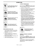
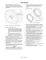
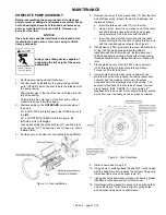
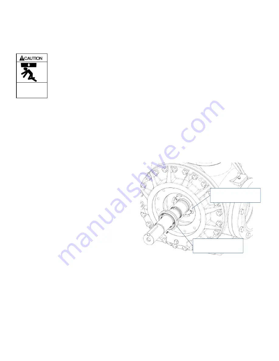
Figure 6 – Seal removal and Installation
9. Remove the remaining mechanical seal parts, including
the seal spring holder, springs, retaining ring, rotating O-
ring and face (153G, 153H, 153N, 153L, 153F) from the
shaft sleeve (154) by removing capscrews (153J).See
Figure 6. Take care to protect the carbon rotating face
from damage during disassembly. Remove and discard
rotating O-ring.
153G
Seal
Spring
Holder,
153J
Retaining
Screws
(4)
154A
Shaft
Sleeve,
155
Retaining
Screws
(2)


