background image

102-A00     page 9/16


MAINTENANCE 

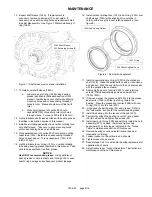
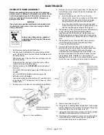
10.  Inspect shaft sleeve (154A).  If replacement is 

necessary, remove capscrews (155), set aside.  If 
necessary, use seal mounting holes as jackscrew holes 
to assist disassembly. See Figure 7 Discard stationary O-
ring (154B).  


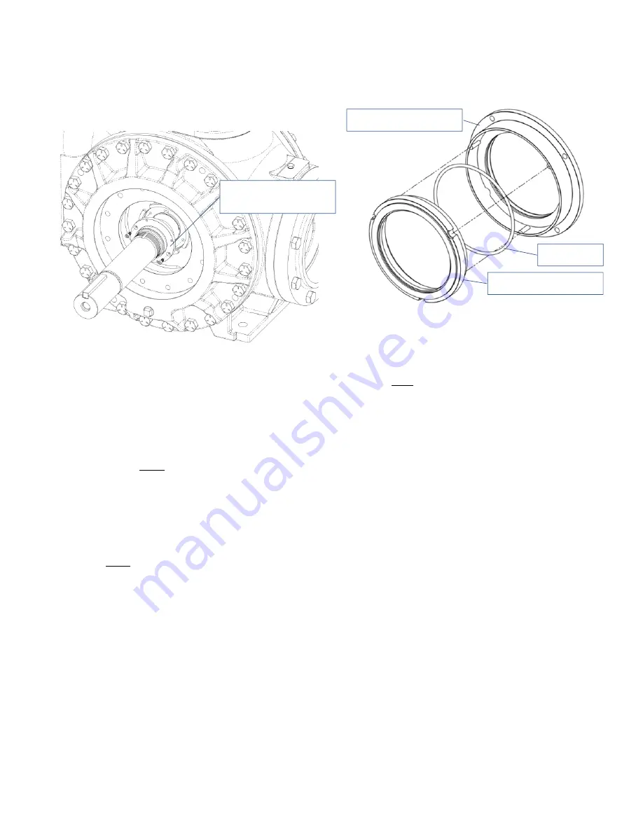
Figure 7 – Shaft sleeve removal and installation 


11.  To install new shaft sleeve (154A): 

a.  Lubricate inner O-ring (154B) using bearing 

grease identified in lubrication section of this 
manual.  Install sleeve over shaft while aligning 
mounting holes with corresponding threaded 
holes in rotor.  Sleeve should mount flush with 
rotor 

b.  Place small amount of Loctite # 220 onto 

capscrews (155), thread fully into rotor holes 
through sleeve.  Torque to 200 inlbf (22.6 Nm). 

12.  Lightly lubricate shaft sleeve surface with bearing grease 

identified in lubrication section of this manual. 

13.  Install seal rotating assembly minus carbon rotating face 

onto shaft sleeve.  Take care to align mounting holes 
with corresponding holes on shaft sleeve. 

14.  Place small amount of Loctite # 220 onto seal mounting 

capscrews (153J). Install into corresponding threaded 
holes on seal sleeve.  Torque capscrews (153J) to 20 
inlbf (2.25 Nm).  

15.  Lightly lubricate inner O-ring (153L) on carbon rotating 

face using bearing grease identified in this manual.  Take 
care to keep seal face free from grease. 

NOTICE

Use ONLY recommended grease.

  Using petroleum 

based grease or oil to lubricate seal O-rings WILL cause 
seal O-ring damage and subsequent product leakage.   

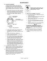
16.  Install carbon rotating face (153F) and O-ring (153L) over 

shaft sleeve (154A) while aligning drive notches in 
carbon with drive pins in seal rotating assembly. (see 
figure 8) 


Figure 8 – Seal carbon alignment 

 
17.  Install a new stationary O-ring (153D) in the stationary 

seat (153B).  Clean the polished face with a clean tissue 
and alcohol.  Push the seat fully into the hub seal recess 
with the polished face outward. 

18.  Apply small amount of Loctite # 220 to seal retaining 

screws.  Install seal retaining screws and washers 
(153Q, 153R). 

19.  If removed, press the grease seal(104A) into the grease 

seal carrier (104b) with the lips facing toward the 
bearing.  Place the grease seal carrier (104B) with new 
O-ring (104C) into the hub (20C). 

20.   Hand pack the ball bearing (24) with grease.  Refer to 

the "Lubrication" section for the recommended grease. 

21.  Install the bearing into the recess of the hub (20C).  
22.  Temporarily attach the bearing cover (27) and gasket 

(26) to hub and hand tighten capscrews (28). 

23.  Install new hub O-ring (72B) and carefully install the hub 

assembly (20C) on head.  Install and tighten hub 
capscrews (21A) torquing as indicated in the “Torque 
Table” in maintenance section of this manual 

24.  Remove bearing cover and install locknut and new 

lockwasher until snug. 

25.  Loosen locknut on the outboard end of pump 
26.  Tighten locknut on near side 

27.  Repeat steps 7-24 for seal and/or bearing replacement of 

opposite side of pump 

28.  Adjust locknuts per “Locknut Adjustment” instructions in 

maintenance section of this manual 


154A


Shaft


Sleeve,


155


Retaining


Screws


(2)


153F


Rotating


Seal


Face


153G


Seal


Spring


Holder


153L


O

ring


Summary of Contents for CRL8A

Page 1: ...his is a SAFETY ALERT SYMBOL When you see this symbol on the product or in the manual look for one of the following signal words and be alert to the potential for personal injury death or major proper...

Page 2: ...eight of the pump assemblies Failure to set the vehicle emergency brake and chock wheels before performing service can cause severe personal injury or property damage Heavy assemblies can cause person...

Page 3: ...e located at least 5 10 pipe diameters from the pump intake 4 Install an intake strainer 5 10 pipe diameters from the pump intake The strainer should have a net open area of at least four times the ar...

Page 4: ...COUNTERCLOCKWISE rotation NOTICE Confirm correct pump rotation by checking the pump rotation arrows respective to pump driver rotation TO CHANGE PUMP ROTATION To change pump rotation the pump must be...

Page 5: ...ng within expected parameters Record the gauge readings in the Initial Start Up Information section of this manual 4 Inspect piping fittings and associated system equipment for leaks noise vibration a...

Page 6: ...pressure relief valve can cause pump component failure personal injury and property damage Hazardous pressure can cause personal injury or property damage Relief valve cap is exposed to pumpage and w...

Page 7: ...CRL8 178 lbs ft 241 Nm 50 lbs ft 68 Nm 50 lbs ft 68 Nm SCHEDULED MAINTENANCE STRAINERS Strainers must be cleaned regularly to avoid pump starvation Schedule will depend upon the application and condi...

Page 8: ...a Bend up the engaged lockwasher tang and rotate the locknut counterclockwise to remove it from the shaft b Slide the lockwasher off the shaft Inspect the lockwasher for damage and replace as require...

Page 9: ...ubsequent product leakage 16 Install carbon rotating face 153F and O ring 153L over shaft sleeve 154A while aligning drive notches in carbon with drive pins in seal rotating assembly see figure 8 Figu...

Page 10: ...4C from the housing in the hub b If worn or damaged remove the grease seal 104A from the carrier 104B c To remove the mechanical seal stationary seat 153B remove the seal retaining screws and washers...

Page 11: ...e three push rods 77 into the rotor b Using a hoist lower the non driven end of the rotor and shaft into the open side of the pump casing being careful not to hit the disc with the shaft c Insert the...

Page 12: ...he bearing Place the grease seal carrier 104B with new O ring 104C into the hub 20C 19 Hand pack the ball bearing 24 with grease Refer to the Lubrication section for the recommended grease 20 Install...

Page 13: ...ang into the slot in the locknut The pump should continue to turn freely when rotated by hand 29 Inspect the grease seal 104 for wear or damage and replace as required Grease the outside diameter of t...

Page 14: ...Damaged or worn parts vanes discs liner or rotor 5 Excessive restriction in discharge line causing partial flow through the relief valve 6 Relief Valve worn set too low or not seating properly 7 Exte...

Page 15: ...ntering the pump 2 Relief valve not opening 3 Hydraulic hammer pressure spikes 4 Pump driver driveline drive shaft misalignment 5 Excessively worn vanes or vane slots SEAL LEAKAGE 1 O rings not compat...

Page 16: ...701 D00 page 16 16 1809 Century Avenue Grand Rapids Michigan 49503 1530 U S A Telephone 616 241 1611 Fax 616 241 3752...

Reviews: