102-A00 page 10/16
MAINTENANCE: HXL6 and HXLJ8 MODELS
5. Remove the vanes (14) and push rods (77) from the rotor
and shaft assembly. Inspect for wear and damage, and
replace as follows:
a. Insert the three push rods (77) into the rotor.
b. Using a hoist, lower the non-driven end of the rotor
and shaft into the open side of the pump casing
being careful not to hit the disc with the shaft.
6. Insert the vanes into the rotor slots with the relief grooves
facing in the direction of pump rotation, and with the
rounded edges outward. See Figure 5. Using a hoist,
install the disc in the casing with the smooth side of the
disc towards the casing (seal cavity outward) and the
pressure relief hole towards the bottom of the casing (6
o’clock position).
7. Install a new head O-ring (72).
8. The mechanical seal and bearing must be installed
before attaching head to pump casing.
a. Apply a small amount of motor oil on the shaft
between the shaft threads and the rotor. Wrap tape
over the shaft threads to prevent damage to
mechanical seal O-rings.
b. Slide the seal jacket assembly over the shaft and
into the seal cavity with the drive tangs of the jacket
towards the rotor. Rotate the jacket assembly to
engage the drive tangs in the rotor slots.
c. Install a new rotating O-ring (153L) in the rotating
seal face (153F). Align and insert the rotating
assembly into the the seal jacket with the polished
face outward. Clean the polished face with a clean
tissue and alcohol. Bronze seal faces should be
oiled during installation, but other seal faces must be
kept clean and dry. Note: Carbon/PTFE rotating
seal face (153M) is installed as a one-piece
assembly.
d. Apply a small amount of motor oil in the seal recess
of the head
e. Install a new stationary O-ring (153D) in the
stationary seat (153B). Clean the polished face with
a clean tissue and alcohol, then push the seat fully
into the seal recess with the polished face outward.
f.
Hand pack the ball bearing (24) with grease. Refer
to the "Lubrication" section for the recommended
grease. Install the bearing into the recess of the
head.
g. Inspect the grease seal (104) for wear or damage
and replace as required. Grease the outside
diameter of the grease seal and push it into the
inboard bearing cover (27A) with the lip of the seal
outward.
h. Attach bearing cover (27A) and gasket (26) to head.
Make sure the grease fittings (76) on the bearing
covers are accessible. Install and torque the
bearing cover capscrews (28) as indicated in the
“Torque Table”.
i.
Using a hoist, carefully attach the head to the
casing. Use care not to damage seal components
during installation. Install and HAND-TIGHTEN the
head capscrews (21).
j.
HXLJ8: Install head studs (21B) and hand-tighten
the nuts (21C).
9. Set the pump upright.
10. Remove the outboard head and disc temporarily
attached earlier.
11. Complete assembly on the OUTBOARD side of the
pump as instructed for the inboard side in steps 6 – 8.
12. Ensure that the pump turns freely. If binding occurs, tap
the rim of the head with a mallet until binding is relieved
and shaft turns freely. Torque head capscrews as
indicated in the “Torque Table” (and studnuts on the
HXLJ8) and recheck for free turning.
13.
RELIEF VALVE ASSEMBLY (if equipped)
a. Insert the valve (9) into the relief valve body(6) with
the fluted end inward.
b. Install the relief valve spring (8), spring guide (7) and
guide rod (45) against the valve.
c. Attach a new relief valve gasket (10) and the valve
cover (4) on the cylinder.
d. Screw the relief valve adjusting screw (2) into the
valve cover until it makes contact with the spring guide
(7).
e. Install the relief valve cap (1) and gasket (88) after the
relief valve has been precisely adjusted.
NOTICE:
The relief valve setting MUST be tested and
adjusted more precisely before putting the pump
into service. Refer to "Relief Valve Setting and
Adjustment"
14. Reinstall coupling, shaft key, and coupling guards.
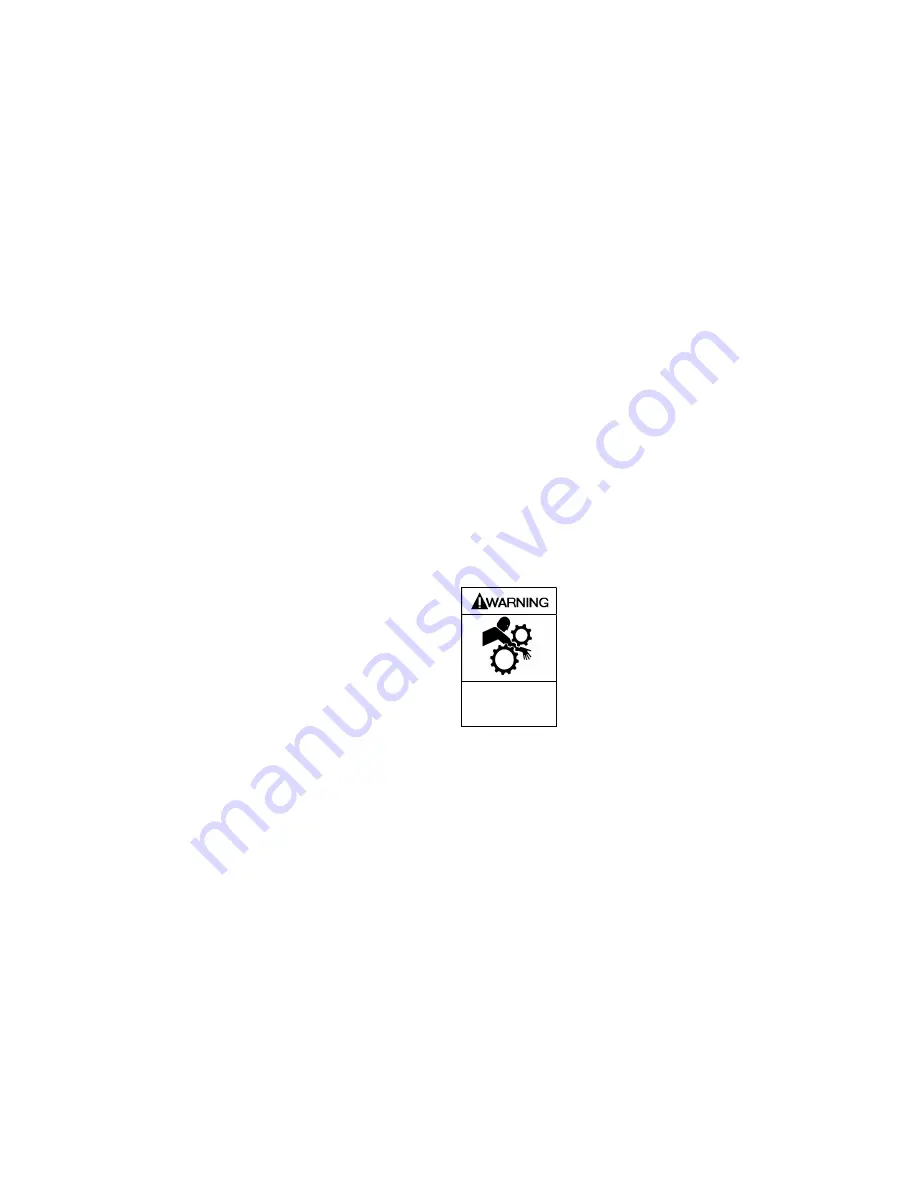
Operation without guards in place can
cause serious personal injury, major
property damage, or death.
Do not operate
without guard in
place.
15. Refer to “Pre-Start Up Check List” and “Start Up
Procedures” sections of this manual prior to pump
operation.


