102-A00 page 11/16
MAINTENANCE: HXL8 and HXL10 MODELS
PUMP DISASSEMBLY – HXL8 and HXL10
NOTICE:
Follow all hazard warnings and instructions provided in
the “Maintenance” section of this manual.
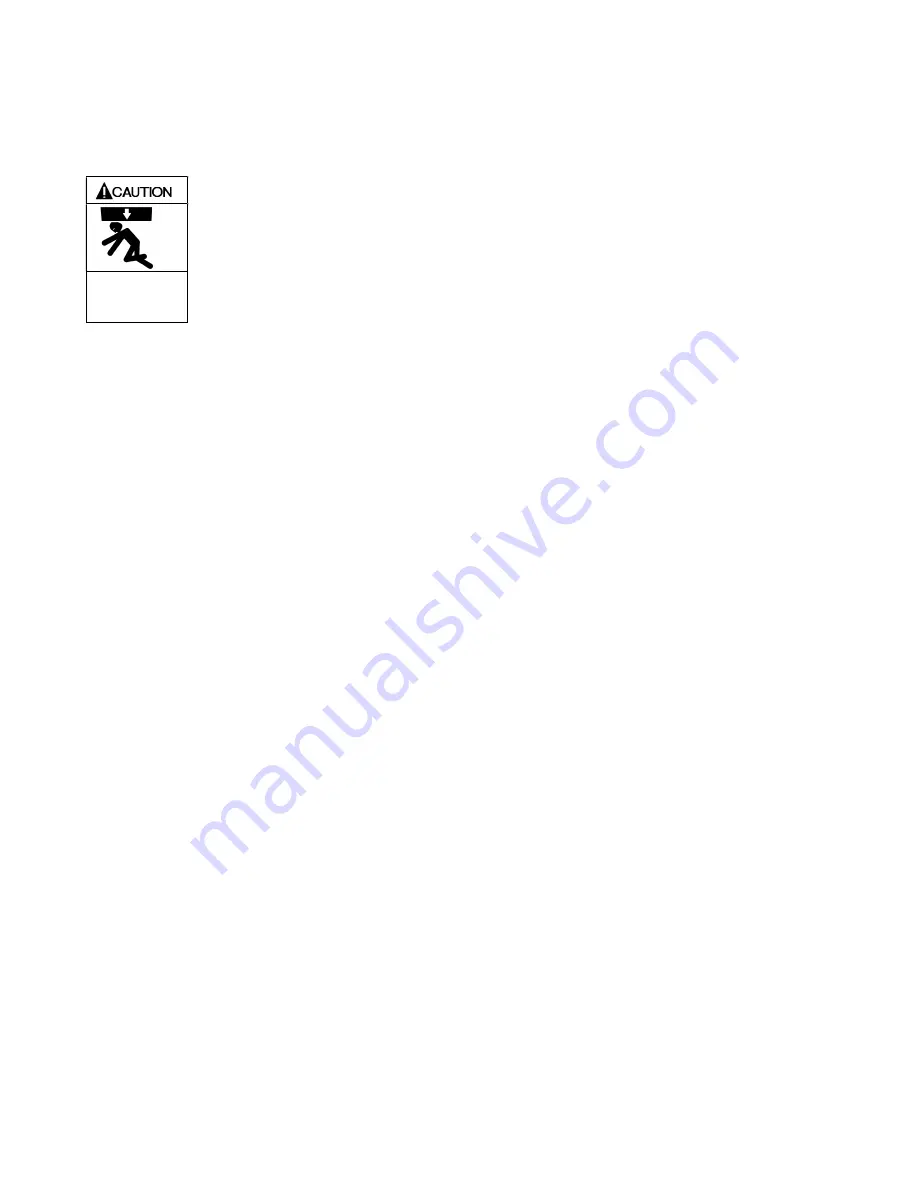
Always use a lifting device capable of
supporting the full weight of the pump
assemblies.
Heavy assemblies can
cause personal injury
or porperty damage.
NOTICE:
Use a hoist and appropriate sling or lifting lugs attached
to the baseplate to lift the entire pump assembly.
Eyebolts attached to the pump, gearbox, or motor must
be used to lift that particular component only.
NOTICE:
Use a hoist and eyebolts installed in the threaded holes
located in the heads, discs, rotor and casing to lift the
heavy pump parts.
Note: If a seal or vanes are to be replaced, the pump may
be left in the upright position. If the rotor-shaft or liner is
to be removed, the pump will have to be placed on its
side for some operations.
1. Flush the pump per instructions in this manual. Drain
and relieve pressure from the pump and system as
required. A 3/4" drain plug (29) is fitted in each head.
2.
With the pump upright.
Clean the pump shaft
thoroughly, making sure the shaft is free of nicks and
burrs. This will prevent damage to the mechanical seal
when the inboard hub or head assembly is removed.
3. Remove the inboard bearing cover capscrews (28) and
slide the inboard bearing cover (27A) and gasket (26) off
the shaft. Discard the bearing cover gasket.
4. Remove the outboard bearing cover capscrews (28) and
slide the outboard bearing cover (27) and gasket (26) off
the shaft. Discard the bearing cover gasket.
5. Removing the locknuts and lockwashers (24A and 24B):
a. Bend up the engaged lockwasher tang and rotate
the locknut counterclockwise to remove it from the
shaft
b. Slide the lockwasher off the shaft. Inspect the
lockwasher for damage and replace as required.
c. Repeat steps a and b on the opposite shaft end.
6. Remove the capscrews from the hub (21A) and slide the
hub assembly off the shaft. The bearing, stationary seat
and stationary O-ring of the mechanical seal (153B,
153D) will come off with the hub.
a. Pull the bearing (24) from the housing in the hub.
b. To remove the mechanical seal stationary seat
(153B), remove the seal retaining screws and
washers (153Q, 153R, 153S) Gently push the
backside of the stationary seat from the seal recess.
Place a cloth under the seal to avoid damage. Be
careful not to contact the polished face of the seal
during removal. Remove and discard mechanical
seal stationary O-ring.
c. Remove the remaining mechanical seal parts,
including the seal jacket and rotating face (153F,
153L, 153G) from the shaft. A piece of stiff wire with
a hook on the end may be used to withdraw the seal
components from the shaft. Remove and discard
rotating O-ring
7. Remove the head capscrews (21). If necessary, place
head capcrews in the two tapped holes near the outer
rim of the head and tighten until the head separates from
the casing. Use a hoist to remove the head from the
casing, being careful not to damage the shaft.
8. HXL8: Remove the head O-ring (72) and disc (71). If
needed, threaded holes are provided in the disc to break
it free.
HXL10: The head O-ring (72) and disc (71) will come off
with the head assembly. Remove the counter sunk set
screws and lockwashers (71A & 71B) to release the disc
from the head. Install an eyebolt in the disc and use a
hoist to remove the disc from the head.
9. Remove the top vane then rotate the shaft by hand to
bring the next vane to the top until all the vanes have
been removed. If the vanes are swollen or jammed in
their slots , the rotor-shaft must be removed.
10. Set the pump on its side with the shaft pointing up.
11. Attach a hoist to rotor-shaft, . lift it out and set it aside.
The pushrods, and rotating portions of the seal will come
out with the rotor-shaft..
12. Set the pump upright.
13. Remove the outboard head components as described fro
the inboard side in steps 6 - 8.
14. HXL10: Remove the four (4) liner retaining screws and
washers (127, 127A) located between the relief valve
ports.
15. Attach a hoist to the liner. Use a block of wood or piece
of brass against the end of the liner, and drive the liner
out of the casing with a hammer by tapping the outside
diameter of the liner.


