background image

501-A00    Page 11/12 

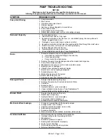
PUMP TROUBLESHOOTING 


NOTICE: 

Maintenance shall be performed by qualified technicians only,  

following the appropriate procedures and warnings as presented in this manual. 


SYMPTOM PROBABLE 

CAUSE 

Pump Not Priming 

1.  Pump not wetted. 
2. Worn 

vanes. 

3.  Internal control valve closed. 
4. Strainer 

clogged. 

5.  Inlet line or valves clogged or too restrictive. 
6. Pump 

vapor-locked. 

7.  Pump speed too low for priming. 
8.  Relief valve partially open, worn or not seating properly. 

Reduced Capacity 

1.  Pump speed too low. 
2.  Internal control valve not fully open. 
3.  Excessive restriction in the inlet line (i.e.: undersized piping, too many elbows & 

fittings, clogged strainer, etc.). 

4.  Damaged or worn parts (vanes, cylinder, or rotor). 
5.  Excessive restriction in discharge line causing partial flow through the relief valve. 
6.  Relief Valve worn, set too low, or not seating properly. 
7.  External Bypass Valve set too low. 
8. Operating 

without 

a vapor return line. 

9.  Vanes installed incorrectly (see "Vane Replacement"). 

Noise 

1.  Excessive pressure drop on the pump due to: 

a.  Undersized or restricted fittings in the inlet line. 
b.  Pump speed too fast. 
c. 

Pump too far from fluid source. 

2.  Running the pump for extended periods with a closed discharge line. 
3.  Pump not securely mounted. 
4.  Misalignment of pump, or motor - base mounted pumps. 
5.  Bearings worn or damaged. 
6.  Vibration from improperly anchored piping. 
7.  Bent shaft, or drive coupling misaligned. 
8.  Excessively worn rotor. 
9.  Malfunctioning valve in the system. 
10. Relief valve setting too low. 
11. Damaged vanes (see following category). 

Damaged Vanes 

1. Foreign 

objects 

entering the pump. 

2.  Running the pump dry for extended periods of time. 
3. Cavitation. 
4. Excessive 

heat. 

5.  Hydraulic hammer - pressure spikes. 
6.  Vanes installed incorrectly (see "Vane Replacement"). 
7. Incompatibility 

with the liquids pumped. 

Broken Shaft 

1. Foreign 

objects 

entering the pump. 

2.  Relief valve not opening. 
3.  Hydraulic hammer - pressure spikes. 
4.  Pump/driver shaft misalignment. 
5.  Excessively worn vanes or vane slots. 

Mechanical Seal Leakage 

1.  O-rings not compatible with the liquids pumped. 
2.  O-rings nicked, cut or twisted. 
3.  Shaft at seal area damaged, worn or dirty. 
4.  Ball bearings overgreased. 
5. Excessive 

cavitation. 

6.  Mechanical seal faces cracked, scratched, pitted or dirty. 

Overload on Motor 

1.  Motor Horsepower not sufficient for application. 
2.  Improper wiring and/or low voltage to motor. 
3. Misalignment 
4.  Excessive pressure or speed. 
5. Bearing 

locknuts 

adjusted improperly. 

6.  Faulty or worn bearings. 
7.  Rotor rubbing against head or cylinder. 
8.  Dirty mechanical seal faces. 


Summary of Contents for LGB1C

Page 1: ...roduct or in the manual look for one of the following signal words and be alert to the potential for personal injury death or major property damage Warns of hazards that WILL cause serious personal in...

Page 2: ...or property damage or death Hazardous or toxic fluids can cause serious injury Do not operate without guard in place PUMP DATA PUMP IDENTIFICATION A pump Identification tag containing the pump serial...

Page 3: ...0 6m from the pump and have a net open area of at least four times the area of the intake piping Strainers must be cleaned regularly to avoid pump starvation 4 The intake and discharge piping system m...

Page 4: ...s Both angular and parallel coupling alignment MUST be maintained between the pump gear motor etc in accordance with manufacturer s instructions See Figure 5 1 Parallel alignment The use of a laser al...

Page 5: ...ons 4 Check for leakage from the piping and equipment 5 Check for excessive noise vibration or overheating of the pump reducer and motor 6 If possible check the flow rate 7 With the manual valve in th...

Page 6: ...e or maintenance NOTICE Maintenance shall be performed by qualified technicians only Follow the appropriate procedures and warnings as presented in this manual Hazardous or toxic fluids can cause seri...

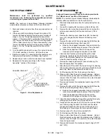
Page 7: ...ocknut 24A and lockwasher 24B from the shaft end protruding through the head 20 a Bend up the engaged lockwasher tang and rotate the locknut counterclockwise to remove it from the shaft b Slide the lo...

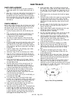
Page 8: ...12 with the bearing cover on the head 13 Apply a light coating of quality O ring lubricant to the shaft end to be inserted into the cylinder 14 Insert the shaft into the cylinder 12 Carefully slide th...

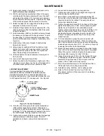
Page 9: ...ollowed by a locknut 24A with the tapered end inward Ensure the inner tang A of the lockwasher is located in the slot in the shaft threads bending it slightly if necessary 39 Tighten both locknuts 24B...

Page 10: ...the relief valve adjusting screw 2 with locknut 3 into the valve cover 4 until it makes contact with the spring guide 7 9 After the relief valve has been adjusted tighten the Locknut 3 NOTICE The reli...

Page 11: ...ended periods with a closed discharge line 3 Pump not securely mounted 4 Misalignment of pump or motor base mounted pumps 5 Bearings worn or damaged 6 Vibration from improperly anchored piping 7 Bent...

Page 12: ...r com for complete information on all Blackmer products 1809 Century Avenue Grand Rapids Michigan 49503 1530 U S A Telephone 616 241 1611 Fax 616 241 3752 E mail blackmer blackmer com Internet Address...

Reviews: