501-A00 Page 5/12
OPERATION
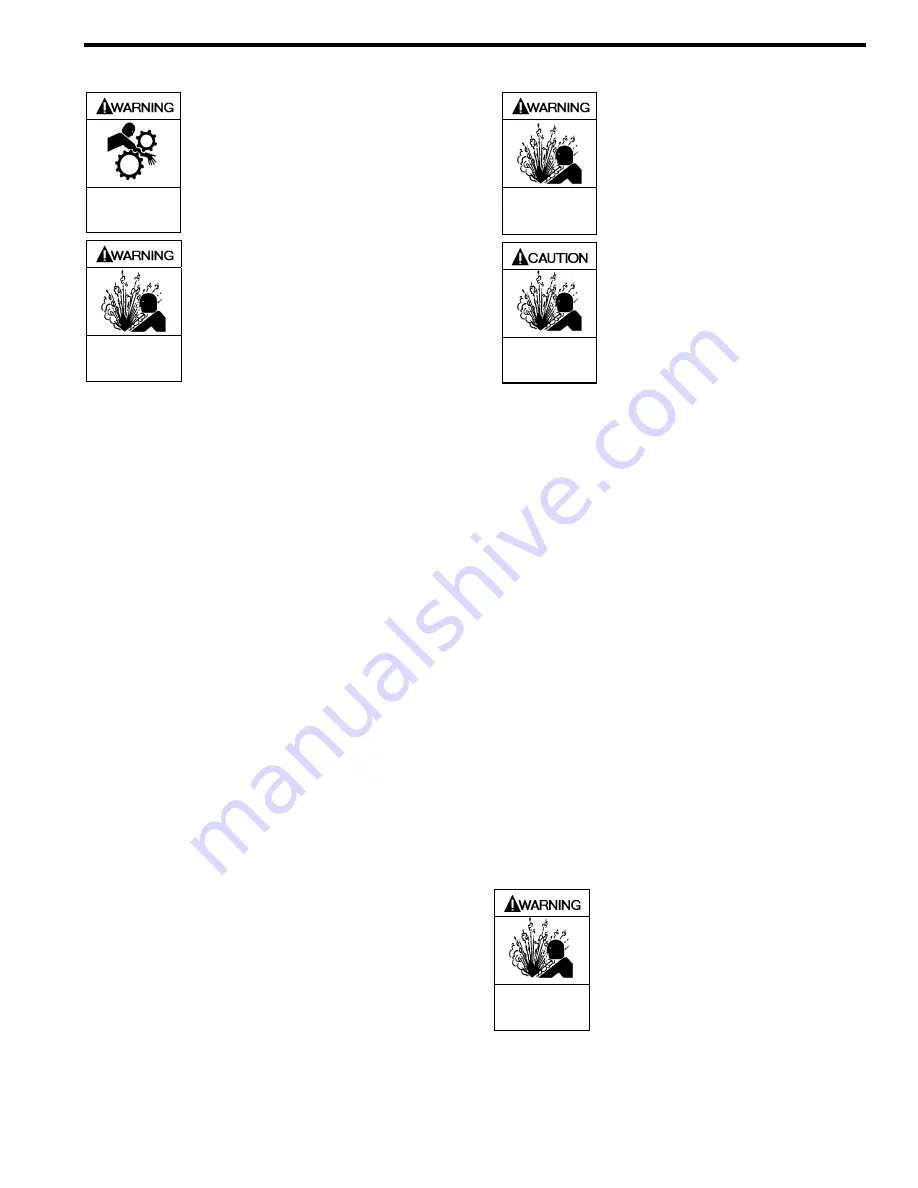
Operation without guards in place can
cause serious personal injury, major
property damage, or death.
Do not operate
without guard
in place
Failure to relieve system pressure
prior to performing pump service can
cause serious personal injury or
property damage.
Systems with
meters will still be pressurized even
after the hose is emptied
Hazardous pressure
can cause serious
personal injury or
property damage
Disconnecting fluid or pressure
containment components during pump
operation can cause serious personal
injury or property damage.
Hazardous pressure
can cause serious
personal injury or
property damage
Pumps operating against a closed
valve can cause system failure,
personal injury and property damage
Hazardous pressure
can cause personal
injury or property
damage
PRE-START UP CHECK LIST
1. Check the alignment of the pipes to the pump. Pipes
should be supported so that they do not spring away or
drop down when pump flanges or union joints are
disconnected.
2. Verify proper coupling alignment.
3. Check the entire pumping system to verify that the proper
inlet and discharge valves are fully open, and that the
drain valves and other auxiliary valves are closed.
4. Install suction and discharge pressure gauges on the
pump in the threaded connections provided. These can
be used to check actual suction and discharge conditions
after pump start-up.
5. Check the wiring of the motor.
6. Briefly start the pump to verify proper rotation direction.
START UP PROCEDURES
NOTICE:
Consult the "General Pump Troubleshooting" section of
this manual if difficulties during start up are experienced.
1. SLOWLY build pressure in the pump.
2. Start the pump. Priming should occur within one minute.
3. Check the suction and discharge pressure gauges to see
if the pump is operating within the expected conditions.
4. Check for leakage from the piping and equipment.
5. Check for excessive noise, vibration or overheating of the
pump, reducer, and motor.
6. If possible, check the flow rate.
7. With the manual valve in the bypass line OPEN, check
the pressure setting of the relief valve by slowly closing a
valve in the discharge line and reading the pressure
gauge. As the valve in the discharge line is closed, the
pump discharge pressure will rise to a maximum value,
then drop back slightly. Use the maximum pressure to
determine the valve setting. This pressure should be 10 -
20 psi (0.7 -1.4 bar) higher than the maximum system
operating pressure. If adjustments need to be made,
refer to the "Relief Valve Setting and Adjustment" section
of this manual.
8. An external bypass valve, if used, must be set at least 25
psi (1.7 bar) lower than the internal pump relief valve.
NOTE: The normal operating pressure must be at least 5
- 15 psi (0.3 -1.0 bar) less than the external bypass valve
setting.
NOTE:
If the pump is operated with both the discharge line
and bypass line closed, the pump will recirculate fluid through
the internal relief valve, causing cavitation and excessive
wear on the pump. The pressure gauge may also read lower
than with normal operation.
RELIEF VALVE SETTING AND
ADJUSTMENT
The relief valve pressure setting is marked on a metal tag
attached to the valve cover. Generally, the relief valve should
be set at least 10 - 20 psi (0.7 - 1.4 Bar) higher than the
operating pressure, or any external bypass valve setting.
DO NOT adjust the relief valve pressure setting while the
pump is in operation.
1.
To INCREASE the pressure setting,
loosen the locknut,
and turn the adjusting screw
inwar
d, or clockwise.
Retighten the locknut
2.
To DECREASE the pressure settin
g, loosen the locknut,
and turn the adjusting screw
outwar
d, or
counterclockwise. Retighten the locknut
Incorrect settings of the pressure relief
valve can cause pump component
failure, personal injury, and property
damage.
Hazardous pressure
can cause serious
personal injury or
property damage


