background image

501-A00    Page 6/12 

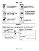
MAINTENANCE:  


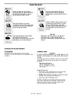
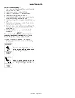
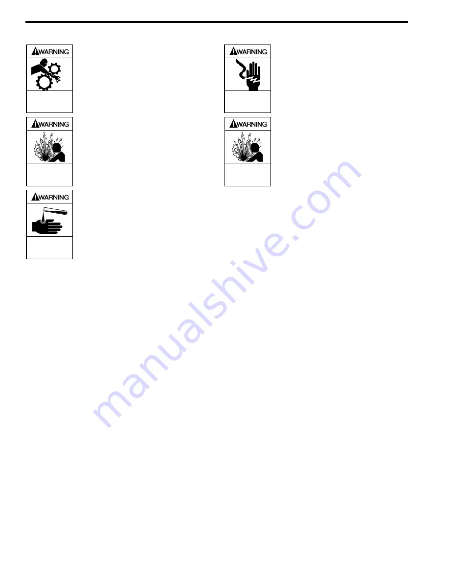
Failure to disconnect and lockout 
electrical power or engine drive before 
attempting maintenance can cause 
severe personal injury or death 


Failure to disconnect and lockout 
electrical power before attempting 
maintenance can cause shock, burns or 
death 


Hazardous 

machinery can 

cause serious 

personal injury.


Hazardous voltage. 

Can shock, burn or 

cause death.


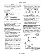
Disconnecting fluid or pressure 
containment components during pump 
operation can cause serious personal 
injury or property damage.


Failure to relieve system pressure prior 
to performing pump service can cause 
serious personal injury or property 
damage.


Systems with meters will still 

be pressurized even after the hose is 
emptied


Hazardous pressure 

can cause serious 

personal injury or 

property damage 


Hazardous pressure 

can cause serious 

personal injury or 

property damage


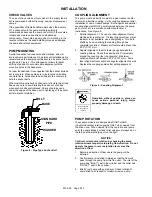
If pumping hazardous or toxic fluids, 
system must be flushed and 
decontaminated, inside and out, prior to 
performing service or maintenance 


NOTICE: 

Maintenance shall be performed by qualified 
technicians only.  Follow the appropriate 
procedures and warnings as presented in this 
manual. 


Hazardous or toxic 

fluids can cause 

serious injury. 


SCHEDULED MAINTENANCE 


STRAINERS 

Strainers must be cleaned regularly to avoid pump 
starvation.  Schedule will depend upon the application and 
conditions. 


LUBRICATION 

NOTICE: 

To avoid possible entanglement in moving parts do not 
lubricate pump bearings or any other parts while pump is 
running 

Pump bearings should be lubricated every one to twelve weeks 
(AT MINIMUM), depending on the application, and operating 
conditions. 

Recommended Grease: 

Mobil® - Mobilgrease XHP222, 
Exxon® - RONNEX MP Grease, 
or equivalent. 


Greasing Procedure: 

1.  Remove the grease relief fittings (76A) from the bearing 

cover (27) and mounting bracket (108 or 108B).  

2. 

SLOWLY 

apply grease with a hand gun until grease begins 

to escape from the grease relief fitting port. 

3.  Replace the grease relief fittings (76A). 

DO NOT overgrease pump bearings. While it is normal for 
some grease to escape from the grease tell-tale hole after 
lubrication, excessive grease on pumps equipped with 
mechanical seals can cause seal failure. 


Summary of Contents for LGB1C

Page 1: ...roduct or in the manual look for one of the following signal words and be alert to the potential for personal injury death or major property damage Warns of hazards that WILL cause serious personal in...

Page 2: ...or property damage or death Hazardous or toxic fluids can cause serious injury Do not operate without guard in place PUMP DATA PUMP IDENTIFICATION A pump Identification tag containing the pump serial...

Page 3: ...0 6m from the pump and have a net open area of at least four times the area of the intake piping Strainers must be cleaned regularly to avoid pump starvation 4 The intake and discharge piping system m...

Page 4: ...s Both angular and parallel coupling alignment MUST be maintained between the pump gear motor etc in accordance with manufacturer s instructions See Figure 5 1 Parallel alignment The use of a laser al...

Page 5: ...ons 4 Check for leakage from the piping and equipment 5 Check for excessive noise vibration or overheating of the pump reducer and motor 6 If possible check the flow rate 7 With the manual valve in th...

Page 6: ...e or maintenance NOTICE Maintenance shall be performed by qualified technicians only Follow the appropriate procedures and warnings as presented in this manual Hazardous or toxic fluids can cause seri...

Page 7: ...ocknut 24A and lockwasher 24B from the shaft end protruding through the head 20 a Bend up the engaged lockwasher tang and rotate the locknut counterclockwise to remove it from the shaft b Slide the lo...

Page 8: ...12 with the bearing cover on the head 13 Apply a light coating of quality O ring lubricant to the shaft end to be inserted into the cylinder 14 Insert the shaft into the cylinder 12 Carefully slide th...

Page 9: ...ollowed by a locknut 24A with the tapered end inward Ensure the inner tang A of the lockwasher is located in the slot in the shaft threads bending it slightly if necessary 39 Tighten both locknuts 24B...

Page 10: ...the relief valve adjusting screw 2 with locknut 3 into the valve cover 4 until it makes contact with the spring guide 7 9 After the relief valve has been adjusted tighten the Locknut 3 NOTICE The reli...

Page 11: ...ended periods with a closed discharge line 3 Pump not securely mounted 4 Misalignment of pump or motor base mounted pumps 5 Bearings worn or damaged 6 Vibration from improperly anchored piping 7 Bent...

Page 12: ...r com for complete information on all Blackmer products 1809 Century Avenue Grand Rapids Michigan 49503 1530 U S A Telephone 616 241 1611 Fax 616 241 3752 E mail blackmer blackmer com Internet Address...

Reviews: