

501-A00 Page 7/12
MAINTENANCE:
VANE REPLACEMENT
NOTICE:
Maintenance shall be performed by qualified
technicians only. Following the appropriate procedures
and warnings as presented in manual.
NOTE:
The numbers in parentheses following individual
parts indicate reference numbers on the Pump Parts List.
1. Drain and relieve pressure from the pump and system as
required.
2. If the pump shaft is protruding through the cylinder (12),
remove the head assembly from the pump according to
steps 4 - 8 in the "Pump Disassembly" section of this
manual. If the pump shaft is protruding through the head
(20), remove the entire pump from the mounting bracket
(108 or 108B) (See Step 3 in "Pump Disassembly") then
remove the head assembly from the pump according to
steps 5 - 8 in the "Pump Disassembly" section of this
manual.
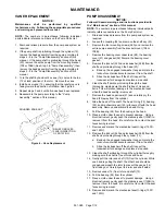
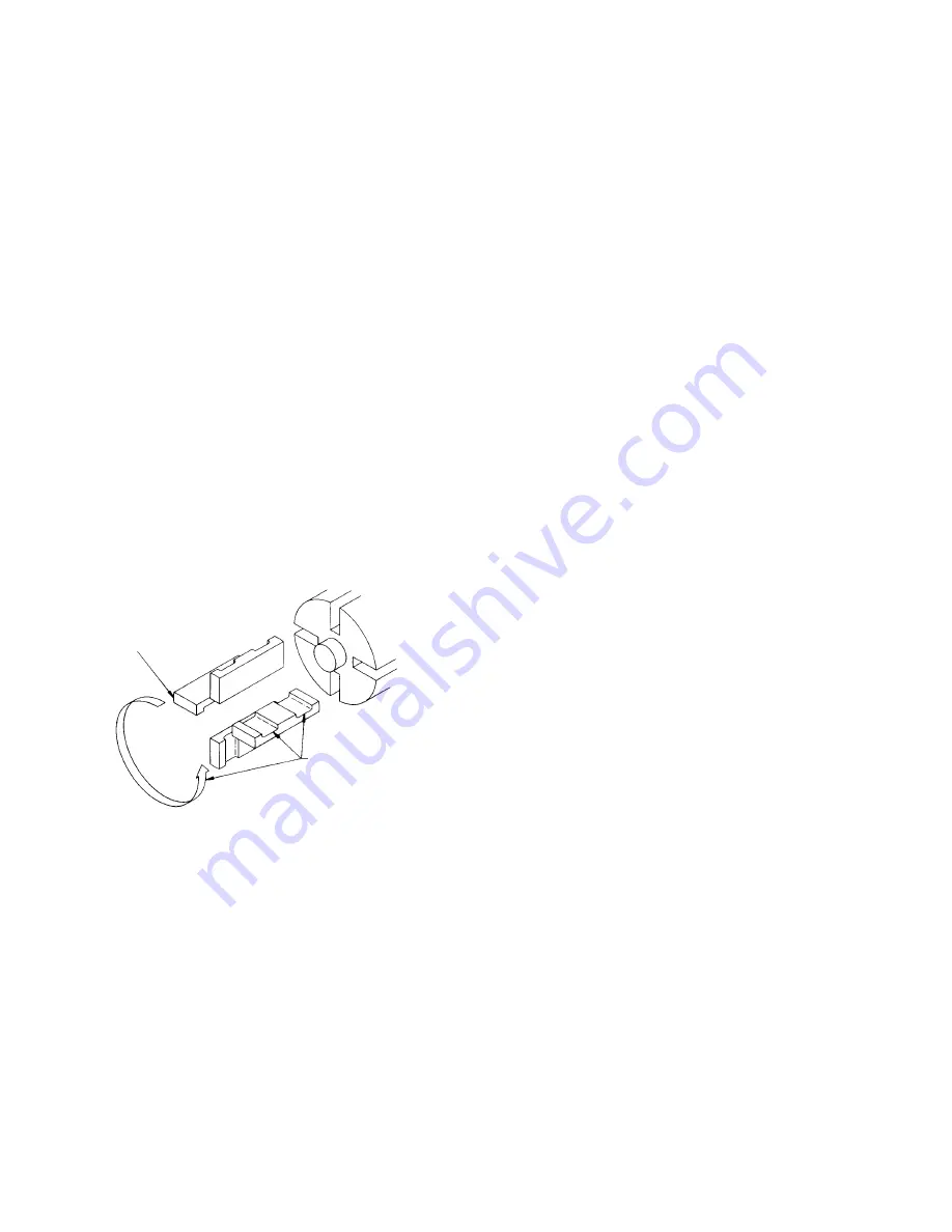
3. Turn the shaft by hand until a vane (14) comes to the top
(12 o'clock) position of the rotor. Remove the vane.
4. Install a new vane (14), ensuring that the relief groove is
facing toward the direction of rotation. See Figure 6.
5. Repeat steps 3 and 4 until all vanes have been replaced.
6. Reassemble the pump according to the "Pump
Assembly." section of this manual.
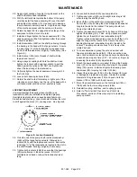
ROUNDED EDGE OUT
RELIEF GROOVES
FACE IN DIRECTION
OF ROTATION
Figure 6 – Vane Replacement
PUMP DISASSEMBLY
NOTICE:
Follow all hazard warnings and instructions provided in
the “Maintenance” section of this manual.
NOTE:
The numbers in parentheses following individual parts
indicate reference numbers on the Pump Parts List.
1. Drain and relieve pressure from the pump and system as
required.
2. Loosen the coupling (34) and remove the shaft key (35).
3. Remove the four mounting screws (28A) and remove the
entire pump assembly from the bracket mount (108 or
108B).
4. Remove the bearing cover capscrews (28), the bearing
cover (27) and gasket (26) Discard the bearing cover
gasket.
5. Remove the locknut (24A) and lockwasher (24B) from the
shaft end protruding through the head (20):
a. Bend up the engaged lockwasher tang and rotate the
locknut counterclockwise to remove it from the shaft.
b. Slide the lockwasher off the shaft. Inspect the
lockwasher for damage and replace as required.
6. Clean the shaft portion protruding through the head
thoroughly, making sure the shaft is free of nicks and
burrs. This will prevent damage to the mechanical seal
when the head assembly is removed.
7. Remove the head capscrews (21) and carefully pry the
head (20) away from the cylinder.
8. Slide the head off the shaft. The head O-ring (72), bearing
(24), and mechanical seal (153) will come off with the head
assembly. Remove and discard the head O-ring.
9. Pull the bearing (24) from the housing in the head.
10. Place a cloth under the seal to prevent damage. Using a
blunt instrument, gently push the stationary seat (153B) to
remove it from the head. Be careful not to contact the seal
faces during removal.
11. Remove and discard the mechanical seal O-rings (153D
and 153G).
12. Remove the locknut (24A) and lockwasher (24B) from the
shaft end protruding through the cylinder (12):
a. Bend up the engaged lockwasher tang and rotate the
locknut counterclockwise to remove it from the shaft.
b. Slide the lockwasher off the shaft. Inspect the
lockwasher for damage and replace as required.
13. Clean the shaft protruding through the cylinder thoroughly,
making sure the shaft is free of nicks and burrs.
14. Gently pull the rotor and shaft (13) from the cylinder. While
one hand is pulling the shaft, the other hand should be
cupped underneath the rotor to prevent the vanes (14)
from falling out. Carefully set the rotor and shaft aside.
15. Remove vanes (14) from rotor and shaft (13).
16. Pull the bearing (24) from the cylinder.
17. Place a cloth under the seal to prevent damage. Using a
blunt instrument, gently push the stationary seat (153B) to
remove it from the head. Be careful not to contact the seal
faces during removal.
18. Remove and discard the mechanical seal O-rings (153D
and 153G).


