background image

103-A00    page 10/12 

PUMP TROUBLESHOOTING 


NOTICE: 

Maintenance shall be performed by qualified technicians only,  

following the appropriate procedures and warnings as presented in this manual. 
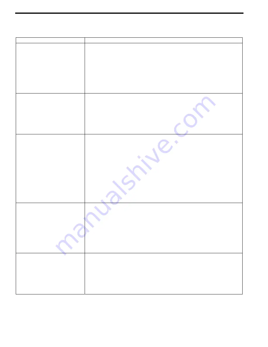
 

SYMPTOM 

PROBABLE CAUSE 

Pump Not Priming 

1.  Pump not wetted. 

2.  Suction valve closed. 

3.  Air leaks in the suction line. 

4.  Strainer clogged. 

5.  Suction line or valves clogged or too restrictive. 

6.  Wrong rotation on motor. 

7.  Broken drive train. 

8.  Pump vapor-locked. 

9.  Pump speed too low for priming. 

10. Worn Vanes. 


Reduced Capacity 

1.  Suction valves not fully open. 

2.  Air leaks in the suction line. 

3.  Excessive restriction in the suction line (i.e.: undersized piping, too many elbows & 

fittings, clogged strainer, etc.). 

4.  Damaged or worn parts. 

5.  Excessive restriction in discharge line causing partial flow through the relief valve. 

6.  Relief Valve worn, set too low, or not seating properly. 

7.  Vanes installed incorrectly (see "Vane Replacement"). 


Noise 

1.  Excessive vacuum on the pump due to: 

a.  Undersized or restricted fittings in the suction line. 

b.  Pump speed too fast for the viscosity or volatility of the liquid. 

c.  Pump too far from fluid source. 

2.  Running the pump for extended periods with a closed discharge line. 

3.  Misalignment of the pump. 

4.  Baseplate not securely mounted. 

5.  Sleeve Bearings (bushings) worn or damaged. 

6.  Vibration from improperly anchored piping. 

7.  Bent shaft, or drive coupling misaligned. 

8.  Excessively worn rotor. 

9.  Malfunctioning valve in the system. 

10. Insufficient oil in the gear reducer. 

11. Damaged vanes (see following category). 


Damaged Vanes 

1.  Foreign objects entering the pump. 

2.  Running the pump dry for extended periods of time. 

3.  Cavitation. 

4.  Viscosity too high for the vanes and /or the pump speed. 

5.  Incompatibility with the liquids pumped. 

6.  Excessive heat. 

7.  Worn or bent push rods, or worn push rod holes. 

8.  Settled or solidified material in the pump at start-up. 

9.  Hydraulic hammer - pressure spikes. 

10. Vanes installed incorrectly (see "Vane Replacement”). 


Broken Shaft 

1.  Foreign objects entering the pump. 

2.  Viscosity too high for the pump speed. 

3.  Relief valve not opening. 

4.  Hydraulic hammer - pressure spikes. 

5.  Pump/driver misalignment. 

6.  Overtightened V-belts, if equipped. 

7.  Excessively worn vanes or vane slots. 

8.  Settled or solidified material in the pump at start-up. 


Summary of Contents for NP1.5B

Page 1: ...NP3 NP4 NPH4 103 A04 103 A05 103 A06 SAFETY DATA This is a SAFETY ALERT SYMBOL When you see this symbol on the product or in the manual look for one of the following signal words and be alert to the...

Page 2: ...ailure to stop the pump before adjusting the shaft packing can cause severe personal injury Hazardous machinery can cause severe personal injury PUMP DATA PUMP IDENTIFICATION A pump Identification tag...

Page 3: ...times the area of the intake piping For viscosities greater than 1 000 SSU 200 cP consult the strainer manufacturer instructions Strainers must be cleaned regularly to avoid pump starvation 4 The int...

Page 4: ...mp driver rotation TO CHANGE PUMP ROTATION To reverse rotation the pump must be disassembled then reassembled with the shaft on the opposite side of the pump See the Maintenance section for instructio...

Page 5: ...arge conditions after pump start up 6 Check the wiring of the motor and briefly turn on the power to make sure that the pump rotates in the direction of the rotation arrow START UP PROCEDURES NOTICE C...

Page 6: ...discharge valve The pump relief valve must be set higher than the system pressure control valve but must not exceed the maximum differential pressure of the pump see table 1 RELIEF VALVE SETTING AND...

Page 7: ...NTENANCE STRAINERS Strainers must be cleaned regularly to avoid pump starvation Schedule will depend upon the application and conditions LUBRICATION NOTICE To avoid possible entanglement in moving par...

Page 8: ...ngs bushings a Using an appropriately sized arbor press remove the old bearing from the head b To aid installation and prevent bearing damage heat the head in an oven at 200oF 93oC before installing t...

Page 9: ...nd uniformly tighten the packing follower stud nuts 18 1 4 turn at a time to reduce leakage b Restart the pump and check the stuffing box temperature several minutes after each adjustment for signs of...

Page 10: ...st for the viscosity or volatility of the liquid c Pump too far from fluid source 2 Running the pump for extended periods with a closed discharge line 3 Misalignment of the pump 4 Baseplate not secure...

Page 11: ...Working Pressure 220 psi 15 17 Bar 195 psi 13 44 Bar LOCATION AND PIPING NOTICE A system pressure control device in addition to the pump relief valve is required OPERATION NOTICE The pump must be tes...

Page 12: ...ess Marine Magnetic Drive Pumps Stainless Steel 14 to 215 GPM Abaque Peristaltic Hose Pumps 0 1 to 210 GPM High Lift Solids Abrasives Reciprocating Gas Compressors Liquefied Gas Transfer B oosting Vap...

Reviews: