103-A00 page 11/12
PUMP TROUBLESHOOTING
….Continued
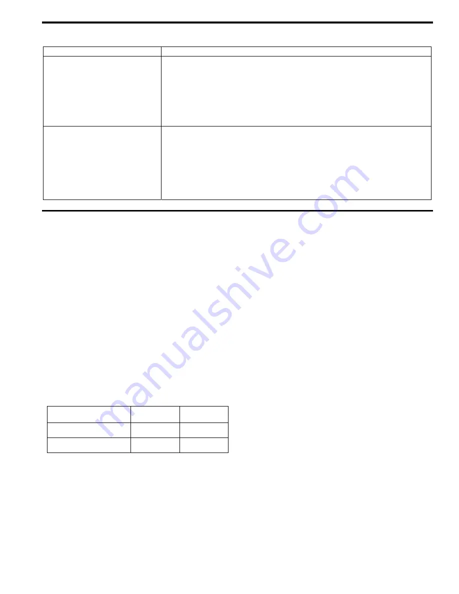
SYMPTOM
PROBABLE CAUSE
Overload on Motor
1. Horsepower of motor not sufficient for application.
2. Improper wire size or wiring.
3. Misalignment.
4. Excessive viscosity, pressure or speed.
5. Faulty or worn sleeve bearings (bushings).
6. Rotor rubbing into head.
7. Excessively tight packing (see “Packing Adjustment”).
8. Unevenly tightened stud nuts, causing shaft interference with packing follower.
Mechanical Seal Leakage
(if equipped)
1. Seal Rings/O-rings not compatible with the liquids pumped.
2. Seal Rings/O-rings nicked, cut or twisted.
3. Shaft at seal area damaged, worn or dirty.
4. Excessive cavitation.
5. Mechanical seal faces cracked, scratched, pitted or dirty.
6. Pump sleeve bearings worn excessively.
NOTE: Consult commercial mechanical seal manufacturer for more information
on mechanical seal troubleshooting.
AFFF SERVICE PUMPS – Special Notes
NOTICE:
Design and materials of construction should be suitable
for use with the type of foam concentrate to minimize
corrosion, foaming, or sticking
NOTICE:
Blackmer NP pumps are not approved for use in systems
where automatic system pressure balance exceeds 200
psi, 13.79 bar (175 psi, 12.07 bar for the NP4, NPH4).
DESCRIPTION
AFFF pumps were previously listed as FFNP models. They
are now NP pumps with specific options:
Duravanes (1.5” – 3”)
Laminate Vanes (4”)
Lip Seal
Corrosion Resistant RV
Stainless Steel 200 psi spring
Buna-N O-Rings
Casing Drain
TABLE 1 – TECHNICAL DATA
1.5”, 2”,
2.5”, 3”
4”
Maximum Differential
Pressure
200 psi
(13.79 Bar)
175 psi
(12.07 Bar)
Maximum Working
Pressure
220 psi
(15.17 Bar)
195 psi
(13.44 Bar)
LOCATION AND PIPING
NOTICE:
A system pressure control device, in addition to the
pump relief valve, is required.
OPERATION
NOTICE:
The pump must be tested, for a ten minute period, every
30 days. During this activity, the pump discharge must
be recirculated through a bypass system. Do not
operate the pump against a closed discharge.
An electrical time clock is recommended to record
elapsed operating time. Refer to the ‘Scheduled
Maintenance - Pump’ section.
PUMP RELIEF VALVE
NOTICE:
The pump’s internal relief valve is designed to protect
only the pump from excessive pressure and must not be
used as a system pressure relief valve. Foam system
pressure must be controlled by a separate bypass
pressure control valve which returns bypassed fluid to
the foam storage tank.
SCHEDULED MAINTENANCE - PUMP
1. Pump MUST be disassembled and checked after each
ten hours of system trial operation, or five years,
whichever occurs sooner. The heads (20 & 23), cylinder
(12), bushing (24) and vanes (14) MUST be inspected
for wear. Replacement of worn parts is required.
Inspect the rotor and shaft for wear or corrosion. If rotor
& shaft indicates wear, scaling, flaking rust particles or
cracking, replacement is required.
2. If during operation of the system the contents of the
foam concentrate tank has been depleted OR there is
reason to believe the pump has run dry, the pump MUST
be completely disassembled and carefully inspected for
damage or wear. The heads (20 & 23), cylinder (12),
bushing (24) and vanes (14) MUST be inspected for
wear. Replacement of worn parts is required. Inspect
the rotor and shaft for wear or corrosion. If rotor & shaft
indicates wear, scaling, flaking rust particles or cracking,
replacement is required.


