


103-A00 page 4/12
INSTALLATION
COUPLING ALIGNMENT
The pump must be directly coupled to a gear and/or driver
with a flexible coupling. Verify coupling alignment after
installation of new or rebuilt pumps. Both angular and parallel
coupling alignment MUST be maintained between the pump,
gear, motor, etc. in accordance with manufacturer’s
instructions. See Figure 3.
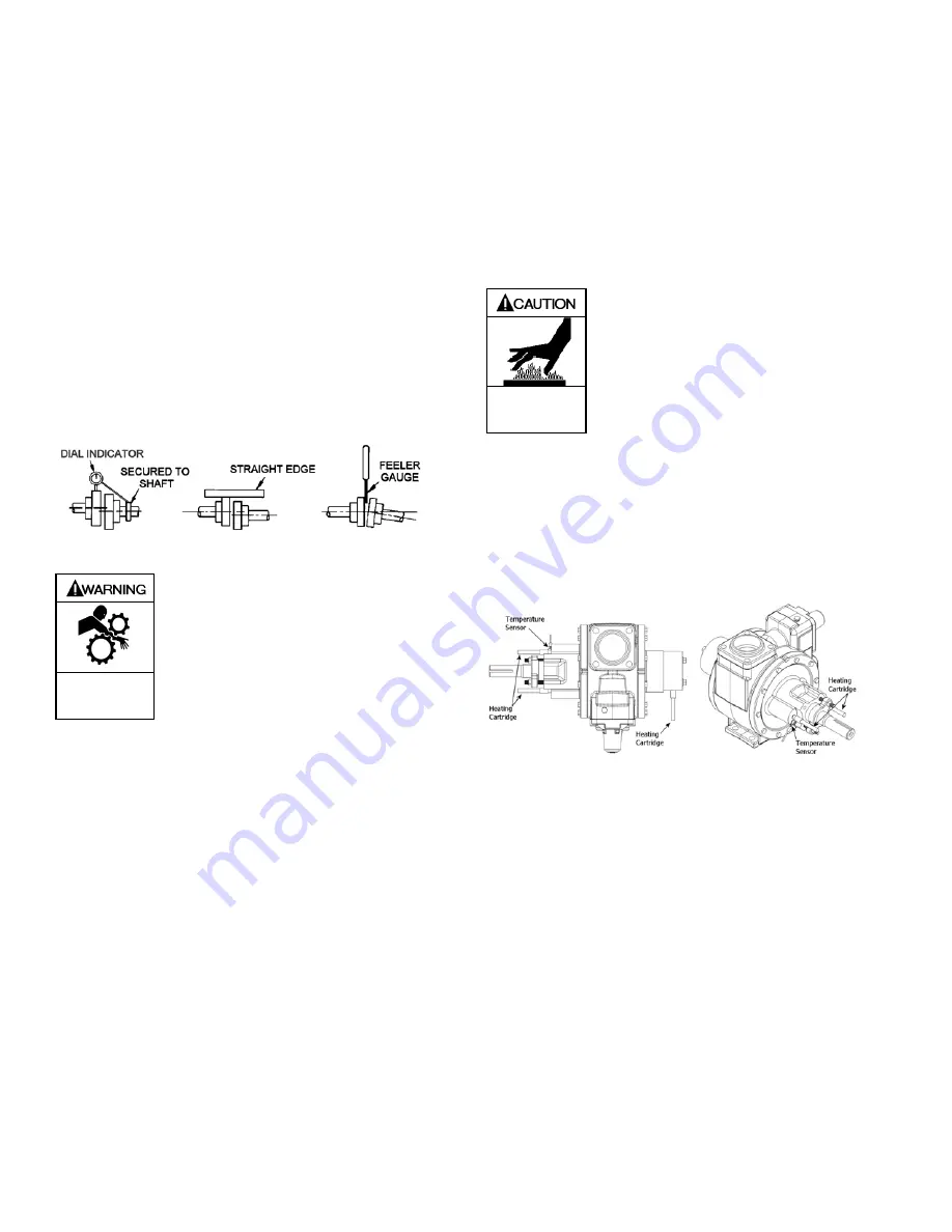
1. Parallel alignment: The use of a laser alignment tool or
dial indicator is preferred. If a laser alignment tool or dial
indicator is not available, use a straightedge. Turn both
shafts by hand, checking the reading through one
complete revolution. Maximum offset should be less than
.005" (.127 mm).
2. Angular alignment: Insert a feeler gauge between the
coupling halves. Check the spacing at 90° increments
around the coupling (four checkpoints). Maximum
variation should not exceed .005" (.127 mm). Some laser
alignment tools will check angular alignment as well.
3. Replace the coupling guards after setting alignment.
Figure 3 – Alignment Check
Operation without guards in place can
cause serious personal injury, major
property damage, or death.
Do not operate
without guard
in place
PUMP ROTATION
A right-hand pump rotates clockwise with the intake on the
right side, when viewed from the driven end.
A left-hand pump rotates counterclockwise with the intake on
the left side, when viewed from the driven end.
NOTICE:
Confirm correct pump rotation by checking the pump
rotation arrows respective to pump driver rotation.
TO CHANGE PUMP ROTATION
To reverse rotation, the pump must be disassembled then
reassembled with the shaft on the opposite side of the pump.
See the ‘Maintenance’ section for instructions.
HEATING HEADS / JACKETS
NOTICE:
Maximum recommended heating jacket steam pressure
is 150 PSI (10.3 bar).
Jacketed heads are recommended for heating highly
viscous liquids, or to “thaw out” liquids that have congealed
in the pumping chamber and packing area.
Hot oil or steam can be circulated through the jacketed
heads by 3/4” NPT connections (3/8” NPT on 1.5” models)
above and below the shaft.
Pumps fitted with heating devices have
hot surfaces that can cause serious
personal injury.
Extreme heat can
cause injury or
property damage.
HEATING HEADS / ELECTRIC
The NP2.5, 3 and 4” pumps may be fitted with heads for
electric heating. The inboard head has two 12.5mm bore
(85 mm deep) Heating Cartridge ports and two M6 x 1.0
(12 mm deep) Temperature Sensor ports. The outboard
bearing cover has one 12.5mm bore (85 mm deep) Heating
Cartridge port. Follow the manufacturer’s instructions when
installing the heating system.
Figure 3a – Heads for Electric Heating
CHECK VALVES
The use of check valves or foot valves in the supply tank is
not recommended with self-priming, positive displacement
pumps.
If the possibility of liquid backflow exists when the pump is
off, a check valve in the pump discharge piping is
recommended because the pump can motor in the reverse
rotation and create undue stress on all attached
components. Never start a pump when it is rotating in the
reverse rotation as the added starting torque can damage
the pump and related equipment.


