103-A00 page 7/12
MAINTENANCE
Failure to disconnect and lockout
electrical power or engine drive before
attempting maintenance can cause
severe personal injury or death
Hazardous
machinery can
cause serious
personal injury.
Failure to relieve system pressure prior
to performing pump service or
maintenance can cause personal injury
or property damage.
Hazardous pressure
can cause personal
injury or property
damage
If pumping hazardous or toxic fluids,
system must be flushed and
decontaminated, inside and out, prior to
performing service or maintenance
Hazardous or toxic
fluids can cause
serious injury.
Failure to disconnect and lockout
electrical power before attempting
maintenance can cause shock, burns or
death
Hazardous voltage.
Can shock, burn or
cause death.
Disconnecting fluid or pressure
containment components during pump
operation can cause serious personal
injury, death or major property damage
Hazardous pressure
can cause personal
injury or property
damage
Failure to stop the pump before
adjusting the shaft packing can cause
severe personal injury
Hazardous
machinery can
cause severe
personal injury.
NOTICE:
Maintenance must follow the indicated schedules, be
performed by qualified technicians only, and follow the
appropriate procedures and warnings as presented in
this manual.
SCHEDULED MAINTENANCE
STRAINERS
Strainers must be cleaned regularly to avoid pump
starvation. Schedule will depend upon the application and
conditions.
LUBRICATION
NOTICE:
To avoid possible entanglement in moving parts do not
lubricate the gear reducer or any other parts while the
pump is running
.
Sleeve bearings (bushings) are lubricated by the liquid being
pumped. Additional lubrication is not required.
IF EQUIPPED: Blackmer gear reducers are shipped from
the factory without oil in the gearcase. Fill with the grade of
oil indicated on the reducer tag. The oil should be changed
after the first 48 hours of use and approximately every 500
hours of use thereafter.
VANE REPLACEMENT
NOTICE:
Maintenance shall be performed by qualified
technicians only. Following the appropriate procedures
and warnings as presented in manual.
1. Drain and flush the pump and system as required.
2. Remove the head assembly and all other parts on the
outboard (non-driven) side of the pump. See the "Pump
Disassembly" Section.
3. Turn the shaft by hand until a vane (14) comes to the
top (12 o'clock) position of the rotor. Remove the vane.
(1.5” and 2” models have only four vanes)
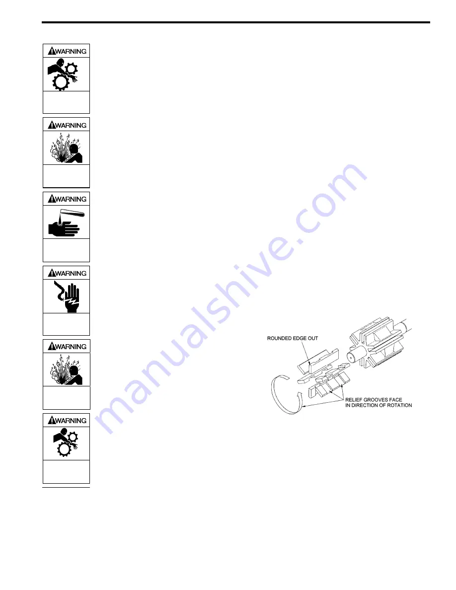
Figure 4 – Vane Replacement
4. Replace the vane, making sure to install the vane with
the rounded edge outward to contact the liner and the
relief grooves facing the direction of rotation.
5. Rotate the shaft until the next rotor slot is in the top
position, and replace the vane. Continue this procedure
until all new vanes are in place.
6. Reassemble the pump as instructed in "Pump
Assembly."


