


103-A00 page 8/12
MAINTENANCE
PUMP DISASSEMBLY
NOTICE:
Follow all hazard warnings and instructions provided in
the “Maintenance” section of this manual.
1. Drain and flush the pump and system as required.
2. Starting on the
inboard
(driven) end of the pump, clean
the pump shaft thoroughly, making sure the shaft is free of
nicks and burrs. This will prevent damage to the lip seal
when the inboard head assembly is removed.
3. Remove the shaft key(35), and the packing follower stud
nuts (18). Slide the packing follower (75) from the shaft.
A slight pry with a screwdriver may be necessary.
4. Pull the packing rings (19) from the stuffing box with the
use of a packing removal tool. Use care not to scratch or
damage the shaft. Discard packing. Remove the pack
washer (58) from the stuffing box.
Note:
If the pump is equipped with a commercial
mechanical seal, refer to the seal manufacturer’s
instructions for removal.
5. Remove the inboard head capscrews (21) and pry the
head assembly away from the cylinder and off the shaft.
Remove head O-ring (72) and discard
6. The sleeve bearing (bushing) (24) is press fit into the head
and should not be removed unless replacement is
necessary. See step 1 of ‘Pump Assembly’.
7. Gently pull the rotor & shaft (13) out of the cylinder. While
one hand is pulling the shaft, the other should be cupped
underneath to prevent the vanes and push rods from
falling out.
8. From the opposite (outboard) side of the pump, remove
the bearing cover capscrews (28), bearing cover (27), and
bearing cover O-ring (26). Discard the O-ring.
9. Remove the outboard head (23) as instructed in steps 4
through 6 above.
PUMP ASSEMBLY
Before reassembling the pump, inspect all component
parts for wear or damage, and replace as required. Wash
out the bearing/seal recess of the head and remove any
burrs or nicks from the rotor and shaft.
1. Inspect the sleeve bearings (bushings) in both heads for
wear or damage and replace as required.
To replace the sleeve bearings (bushings):
a. Using an appropriately sized arbor press, remove the old
bearing from the head.
b. To aid installation and prevent bearing damage, heat the
head in an oven at 200
o
F (93
o
C) before installing the
bearing.
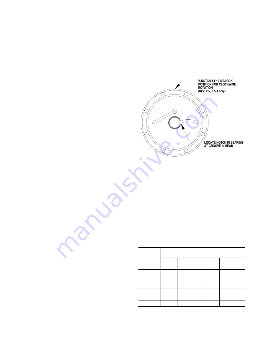
c. Coat the bearing with grease and place it on the inside
face of the head, with the notched end UP. Align the
notch in the bearing with the groove in the head (see
Figure 5).
d. Using an arbor press, press the bearing into the head in
one continuous motion, until it is flush with the inside face
of the head or slightly recessed (.015" maximum).
NOTE:
Ensure the bearing does not become misaligned during
the pressing motion. Starting and stopping the pressing
motion may result in a cracked bearing.
2. Reassemble the
OUTBOARD
side of the pump first:
For a CLOCKWISE rotation pump, position the pump
cylinder with the INTAKE port to the
left
.
For a COUNTERCLOCKWISE rotation pump,
position the pump cylinder with the INTAKE port to
the
right
.
3. Apply a small amount of quality O-ring lubricant on a new
head O-ring (72), and install in the groove on the inside
face of the outboard head (23).
Figure 5 – Bearing Location
4. For NP1.5: Place INTAKE marking on outboard head
towards INTAKE of pump.
NOTE
: V-notch location does
not apply to this model.
NP2, 2.5,3 AND 4: For clockwise (right-hand) rotation,
place the outboard head (23) on the cylinder with the V-
notch upward, in the 12 o'clock position. For
counterclockwise (left-hand) rotation, place the outboard
head (23) on the cylinder with the V-notch downward, in
the 6 o'clock position.
5. Install the head capscrews (21) and uniformly tighten;
torque per the Bolt Torque Table.
6. Install a new bearing cover O-ring (26) and attach the
bearing cover (27) to the outboard head. Install and
uniformly tighten the bearing cover capscrews (28);
torque per the Bolt Torque Table.
BOLT TORQUE TABLE
Model
Head
Capscrew
Bearing Cover
Capscrew
Size
Torque
ft-lb (Nm)
Size
Torque
ft-lb (Nm)
NP1.5
3/8"
25 (34)
5/16"
15 (20)
NP2
3/8"
25 (34)
3/8"
25 (34)
NP2.5
3/8"
25 (34)
3/8"
25 (34)
NP3
3/8"
25 (34)
3/8"
25 (34)
NP4
1/2"
58 (79)
5/8"
115 (156)
NPH4
1/2"
58 (79)
5/8"
115 (156)
7. Turn the pump around and begin assembly on the
opposite, inboard end.


