

BLACKMER POWER PUMPS
965820
Page 1/16
INSTRUCTIONS NO. 111-B00
INSTALLATION OPERATION AND MAINTENANCE INSTRUCTIONS
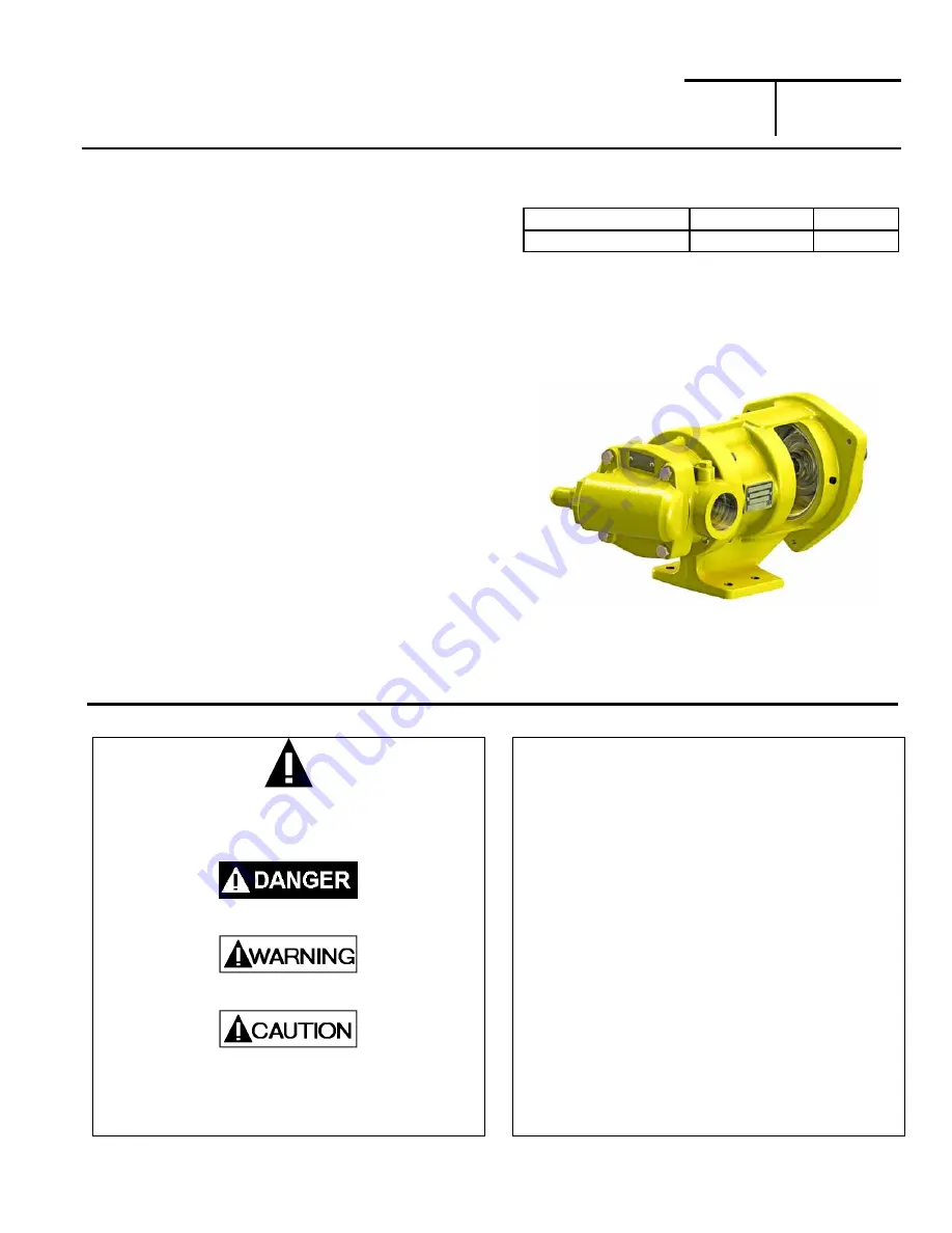
ProVane
®
Models: PV6B, 8B
Section
Effective
Replaces
111
Feb 2013
Dec 2007
Patent Protected by U.S. Patents 7134855 & 7316551 B2 and Related Foreign Patents.
TABLE OF CONTENTS
Page
General
Safety Data ................................................1-2
PUMP DATA
Initial Pump Start Up Information ................................ 2
Technical
Data ........................................................... 2
INSTALLATION
Pre-Installation Cleaning ............................................ 3
Location
and
Piping .................................................... 3
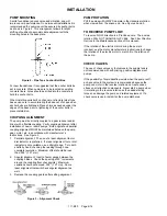
Mounting .................................................................... 4
Coupling
Alignment .................................................... 4
Pump
Rotation............................................................ 4
To Reverse Pump Rotation ........................................ 4
Check
Valves ............................................................. 4
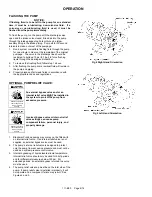
OPERATION
Pre-Start Up Check List .............................................. 5
Start Up Procedures ................................................... 5
Running the Pump in Reverse .................................... 5
Flushing
the Pump ..................................................... 6
Optional
Pump
Relief Valve........................................ 6
Optional Relief Valve Setting and Adjustment ............ 7
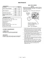
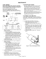
MAINTENANCE
Torque Table ................................................................. 8
Lubrication ..................................................................... 8
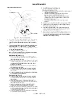
Strainers ........................................................................ 8
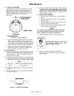
Vane Replacement ........................................................ 8
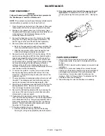
Pump Disassembly ....................................................... 9
Parts Replacement ........................................................ 9
Pump Assembly .......................................................... 10
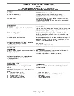
TROUBLE SHOOTING
...................................................... 13
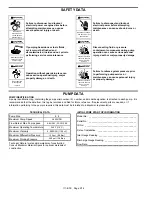
ONLY Pump models listed below are covered in this Manual
Cylinder Type Models
Material
Parts List
PV6B, PV8B
Ductile Iron
111-B01
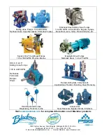
Blackmer manuals and parts lists may be obtained from
Blackmer's website (www.blackmer.com) or by contacting
Blackmer Customer Service.
Numbers in parentheses following individual parts indicate
reference numbers on Blackmer Part Lists.
SAFETY DATA
This is a SAFETY ALERT SYMBOL.
When you see this symbol on the product, or in the manual,
look for one of the following signal words and be alert to the
potential for personal injury, death or major property damage
Warns of hazards that WILL cause serious personal injury,
death or major property damage.
Warns of hazards that CAN cause serious personal injury,
death or major property damage.
Warns of hazards that CAN cause personal injury
or property damage.
NOTICE:
Indicates special instructions which are very
important and must be followed.
NOTICE:
Blackmer Pumps
MUST
only be installed in systems, which
have been designed by qualified engineering personnel. The
system
MUST
conform to all applicable local and national
regulations and safety standards.
This manual is intended to assist in the installation and
operation of the Blackmer ProVane pumps, and
MUST
be
kept with the pump.
Pump service shall be performed by qualified technicians
ONLY
. Service shall conform to all applicable local and
national regulations and safety standards.
Thoroughly review this manual, all instructions and hazard
warnings,
BEFORE
performing any work on the pump.
Maintain
ALL
system and pump operation and hazard
warning decals.
Summary of Contents for ProVane PV6B
Page 15: ...111 B00 Page 15 16 NOTES...


