background image

111-B00     Page 12/16 

MAINTENANCE: 

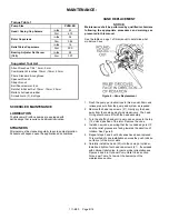
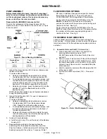
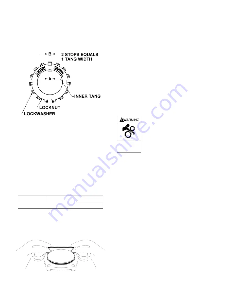
14. LOCKNUT ADJUSTMENT 

It is important that the bearing locknut (24A) and lock 
washer (24B) be installed and adjusted properly. Over 
tightening the locknut can cause bearing failure or a 
broken lock washer tang. A loose locknut will allow the 
rotor to shift within the pump, causing wear.  
See Figure 12. 


Figure 12 – Locknut Assembly 

a.  On the end of the pump shaft, install a lock washer 

(24B) with the tangs facing outward, followed by a 
locknut (24A) with the tapered end inward. Ensure the 
inner tang "A" of the lock washer is located in the slot 
in the shaft threads, bending it slightly, if necessary. 

b.  Tighten the locknut to ensure that the bearing is 

bottomed in the recess. DO NOT over tighten and 
bend or shear the lock washer inner tang. 
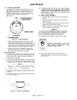
Bearing Adjustment  

15.  Turn the bearing adjuster counterclockwise, as viewed 

from the driven end of the pump, until the shaft is snug 
and no longer turns.  Mark a line across the bearing 
adjuster and drive housing. 

16.  Turn the bearing adjuster clockwise, as viewed from the 

driven end of the pump the distance prescribed per table 
2.  Measurement to be taken on outside of drive housing.  

Table 2 

Pump size 

Distance on OD of Drive Housing 

PV 6,8 

3/4” (19.05 mm) 

17.  Tighten the bearing adjuster lock setscrews and torque 

per table 1. 

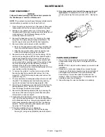
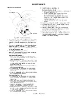
18.  Install a new head O-ring (72) on the dowel of the head 

as shown in Figure 13. 


Figure 13 – Head O-ring Installation 


19. 

Carefully install the head (23) into the cylinder.  

If pump 

is equipped with internal relief valve, orient the relief 
valve per instruction in PUMP RELIEF VALVE section 
of this manual. 

 Install and tighten four head cap screws 

(21A).  Torque per table 1.


20.  RELIEF VALVE ASSEMBLY 

a.  Insert the valve into the valve body with the fluted in 

inward. 

b.  Install the relief valve spring onto valve and spring 

guide onto spring. 

c.  Screw the adjusting screw into the valve cover until it 

makes contact with the spring guide 

d.  Install the relief valve cap and O-ring after the relief 

valve has been properly adjusted. 

NOTICE: 

The relief valve setting MUST be tested and adjusted 
more precisely before putting the pump into service.  
Refer to “Relief Valve Setting and Adjustment”. 

21.  Reinstall coupling, shaft key, and coupling guards.  


Operation without guards in place can 
cause serious personal injury, major 
property damage, or death. 

Do not operate 

without guard 

in place 


22.  Refer to “Pre-Start Up Check List” and “Start Up 

Procedures” sections of this manual prior to restarting 
pump operation. 


Summary of Contents for ProVane PV6B

Page 1: ...vice Numbers in parentheses following individual parts indicate reference numbers on Blackmer Part Lists SAFETY DATA This is a SAFETY ALERT SYMBOL When you see this symbol on the product or in the man...

Page 2: ...in place Hazardous pressure can cause personal injury or property damage PUMP DATA PUMP IDENTIFICATION A pump Identification tag containing the pump serial number I D number and model designation is...

Page 3: ...nd installation of the piping system review the following suggestions 1 Locate the pump as near as possible to the source of supply to avoid excessive inlet pipe friction 2 The inlet line should be at...

Page 4: ...ot available use a straight edge Turn both shafts by hand checking the reading through one complete revolution Maximum offset should be less than 005 127 mm 2 Angular alignment Insert a feeler gauge b...

Page 5: ...alves are fully open and that the drain valves and other auxiliary valves are closed 4 Install inlet and discharge pressure gauges on the pump in the threaded connections provided These can be used to...

Page 6: ...tions OPTIONAL PUMP RELIEF VALVE An external bypass valve and or an internal relief valve MUST be installed in the system to protect the pump from excessive pressure Hazardous pressure can cause perso...

Page 7: ...ce as required Reattach R V cap O ring and RV cap Refer to the individual Blackmer pump parts lists for various spring pressure ranges Unless specified otherwise pumps are supplied from the factory wi...

Page 8: ...ed in this manual See the table on page 1 of this manual to determine what model you have Figure 6 Vane Replacement 1 Flush the pump per instructions in this manual Drain and relieve pressure from the...

Page 9: ...pward and remove the 4 cap screws 21 Lift off the bearing housing and remove the cylinder O ring 71 7 The mechanical seal rotating assembly will come out with the shaft The stationary seat and station...

Page 10: ...ace of bearing press the OD of the bearing into the bearing adjuster until fully seated 3 Cylinder O ring installation a Install a new O ring 71 over the dowel of the Bearing housing 57 4 Reassemble t...

Page 11: ...are installed carefully insert the driven end of rotor and shaft into the cylinder b Apply a small amount of Flowserve Pac Ease or equivalent water based lubricant on the shaft between the shaft end a...

Page 12: ...housing Table 2 Pump size Distance on OD of Drive Housing PV 6 8 3 4 19 05 mm 17 Tighten the bearing adjuster lock setscrews and torque per table 1 18 Install a new head O ring 72 on the dowel of the...

Page 13: ...the seal faces will prevent the faces from mating properly causing the rotor and shaft to bind or turn hard Use a tissue paper alcohol to clean the seal faces NOTE Apply a light oil or suitable lubric...

Page 14: ...use Air leaks in the suction line Restriction in the suction line Damaged or worn pump parts Too much lift for the vapor pressure of the fluid A dirty or clogged strainer Worn vanes Suction Valve Clos...

Page 15: ...111 B00 Page 15 16 NOTES...

Page 16: ...215 GPM HXL 6 8 10 Sliding Vane Pumps 130 to 2 220 GPM Refineries Terminals Barges Ships Reciprocating Gas Compressors Liquefied Gas Transfer Boosting Vapor Recovery Hand Operated Pumps Dispensing Tra...

Reviews: