background image

111-B00    Page 14/16 


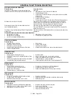
GENERAL PUMP TROUBLESHOOTING 


EXCESSIVE NOISE AND VIBRATION 


Probable Cause 

Corrective Action 

Cavitation or vaporization of the liquid resulting from 
excessive vacuum on the pump due to starved suction. 

Check for: 


Inlet piping too long or too small in diameter.  


Strainer plugged or dirty.  


Undersized or restrictive fittings, such as globe valves or partially 
closed valves. 


Excessive amount of elbows.  


Suction lift too great.  


Pump speed too high for the viscosity of the liquid being pumped. 


Entrained air or vapors in the pump. 

Check pipe joints for leakage of air. Sometimes when recirculating 
liquid in a tank, the returning liquid falling through the air carries air 
down into the tank, which eventually gets back into the pump. 


Pump speeds exceed the recommended maximum. 

Check the recommended RPM for your specific application. 


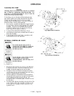
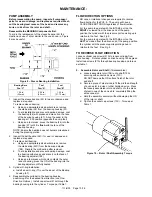
Liner Installed Backwards 

The word “INTAKE”, which is cast on the liner MUST be towards the 
intake side of the pump 


Continual or long term bypassing of liquid through system 
bypass valve. 

Check for restriction in the discharge line, or an improper bypass valve 
adjustment 


OTHER POSSIBLE CAUSES OF NOISE AND VIBRATION: 


Excessively worn vanes 


Bearing Worn or Damaged. 


Loose or improperly installed piping.  


Misalignment of pump and driver. 


Pump base not properly mounted. 


POOR OR NO PRIMING 


Probable Cause 


Air leaks in the suction line.  


Restriction in the suction line.  


Damaged or worn pump parts.  


Too much lift for the vapor pressure of the fluid.  


A dirty or clogged strainer.  


Worn vanes.  


Suction Valve Closed.  


Incorrect pump rotation  


Bypass Valve partially open, valve not seating properly. 


DAMAGED VANES 


Probable Cause 


Foreign objects entering the pump. 


Running the pump dry for extended periods of time. 

 Cavitation. 


Viscosity too high for the vanes and/or pump speed. 


Incompatibility with the liquids pumped. 


 Excessive 

heat. 


Worn or bent push rods, or worn push rod holes. 


Settled or solidified material in the pump at start-up. 


Hydraulic hammer - pressure spikes. 


Vanes installed incorrectly (see “Vane Replacement"). 


BROKEN SHAFT 


Probable Cause 


Foreign objects entering the pump. 


Viscosity too high for the pump speed. 


Bypass valve not opening. 


Hydraulic hammer - pressure spikes. 


 Pump/driver, 

driveline/drive shaft misalignment. 


Excessively worn vanes or vane slots. 


Settled or solidified material in the pump at start-up. 


SEAL LEAKAGE 


Probable Cause 


O-rings not compatible with the liquids pumped. 


O-rings nicked, cut or twisted. 


Shaft at seal area damaged, worn or dirty. 


 Excessive 

cavitation. 


Mechanical seal faces cracked, scratched, pitted or dirty. 


Ball bearings worn. 


MOTOR OVERLOAD 


Probable Cause 


Horsepower of motor not sufficient for application 


Improper wire size / wiring and/or voltage to motor. 


Misalignment in pump drive system. 


 Excessive 

viscosity, 

pressure or speed. 


Faulty or worn bearings. 


Rotor rubbing against head or liner. 


Dirty mechanical seal faces. 

Summary of Contents for ProVane PV6B

Page 1: ...vice Numbers in parentheses following individual parts indicate reference numbers on Blackmer Part Lists SAFETY DATA This is a SAFETY ALERT SYMBOL When you see this symbol on the product or in the man...

Page 2: ...in place Hazardous pressure can cause personal injury or property damage PUMP DATA PUMP IDENTIFICATION A pump Identification tag containing the pump serial number I D number and model designation is...

Page 3: ...nd installation of the piping system review the following suggestions 1 Locate the pump as near as possible to the source of supply to avoid excessive inlet pipe friction 2 The inlet line should be at...

Page 4: ...ot available use a straight edge Turn both shafts by hand checking the reading through one complete revolution Maximum offset should be less than 005 127 mm 2 Angular alignment Insert a feeler gauge b...

Page 5: ...alves are fully open and that the drain valves and other auxiliary valves are closed 4 Install inlet and discharge pressure gauges on the pump in the threaded connections provided These can be used to...

Page 6: ...tions OPTIONAL PUMP RELIEF VALVE An external bypass valve and or an internal relief valve MUST be installed in the system to protect the pump from excessive pressure Hazardous pressure can cause perso...

Page 7: ...ce as required Reattach R V cap O ring and RV cap Refer to the individual Blackmer pump parts lists for various spring pressure ranges Unless specified otherwise pumps are supplied from the factory wi...

Page 8: ...ed in this manual See the table on page 1 of this manual to determine what model you have Figure 6 Vane Replacement 1 Flush the pump per instructions in this manual Drain and relieve pressure from the...

Page 9: ...pward and remove the 4 cap screws 21 Lift off the bearing housing and remove the cylinder O ring 71 7 The mechanical seal rotating assembly will come out with the shaft The stationary seat and station...

Page 10: ...ace of bearing press the OD of the bearing into the bearing adjuster until fully seated 3 Cylinder O ring installation a Install a new O ring 71 over the dowel of the Bearing housing 57 4 Reassemble t...

Page 11: ...are installed carefully insert the driven end of rotor and shaft into the cylinder b Apply a small amount of Flowserve Pac Ease or equivalent water based lubricant on the shaft between the shaft end a...

Page 12: ...housing Table 2 Pump size Distance on OD of Drive Housing PV 6 8 3 4 19 05 mm 17 Tighten the bearing adjuster lock setscrews and torque per table 1 18 Install a new head O ring 72 on the dowel of the...

Page 13: ...the seal faces will prevent the faces from mating properly causing the rotor and shaft to bind or turn hard Use a tissue paper alcohol to clean the seal faces NOTE Apply a light oil or suitable lubric...

Page 14: ...use Air leaks in the suction line Restriction in the suction line Damaged or worn pump parts Too much lift for the vapor pressure of the fluid A dirty or clogged strainer Worn vanes Suction Valve Clos...

Page 15: ...111 B00 Page 15 16 NOTES...

Page 16: ...215 GPM HXL 6 8 10 Sliding Vane Pumps 130 to 2 220 GPM Refineries Terminals Barges Ships Reciprocating Gas Compressors Liquefied Gas Transfer Boosting Vapor Recovery Hand Operated Pumps Dispensing Tra...

Reviews: