

111-B00 Page 8/16
MAINTENANCE:
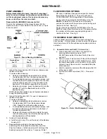
Torque Table 1
Pump Size
PV6B, 8B
Head / Casing Cap Screws
in-lbs 42
N-m 4.75
Rotor Capscrews
in-lbs 34
N/m 3.84
Relief Valve Capscrews
in-lbs 15
N-m 20.3
Bearing Adjuster Set Screw
(189)
in-lbs 9.5
N-m 1.07
Suggested Tool List
Allen Wrenches: 7/64”, 2mm - 5mm
Combination Wrenches: 10mm - 12mm, 23mm
Pliers: Standard & Long Nose
Spanner Wrench
Strap Wrench
Ball Peen Hammer: 8oz.
Ratchet & Socket Set: 10mm - 12mm, 23mm
Mallet: shot loaded rubber
Screwdrivers: (2), slot type
SCHEDULED MAINTENANCE
LUBRICATION
The Blackmer ProVane pumps are equipped with
ball bearings that require no additional lubrication.
STRAINERS
Strainers must be cleaned regularly to avoid pump starvation.
Schedule will depend upon the application and conditions.
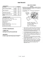
VANE REPLACEMENT
NOTICE:
Maintenance shall be performed by qualified technicians
following the appropriate procedures and warnings as
presented in this manual.
See the table on page 1 of this manual to determine what
model you have.
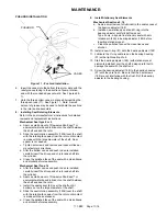
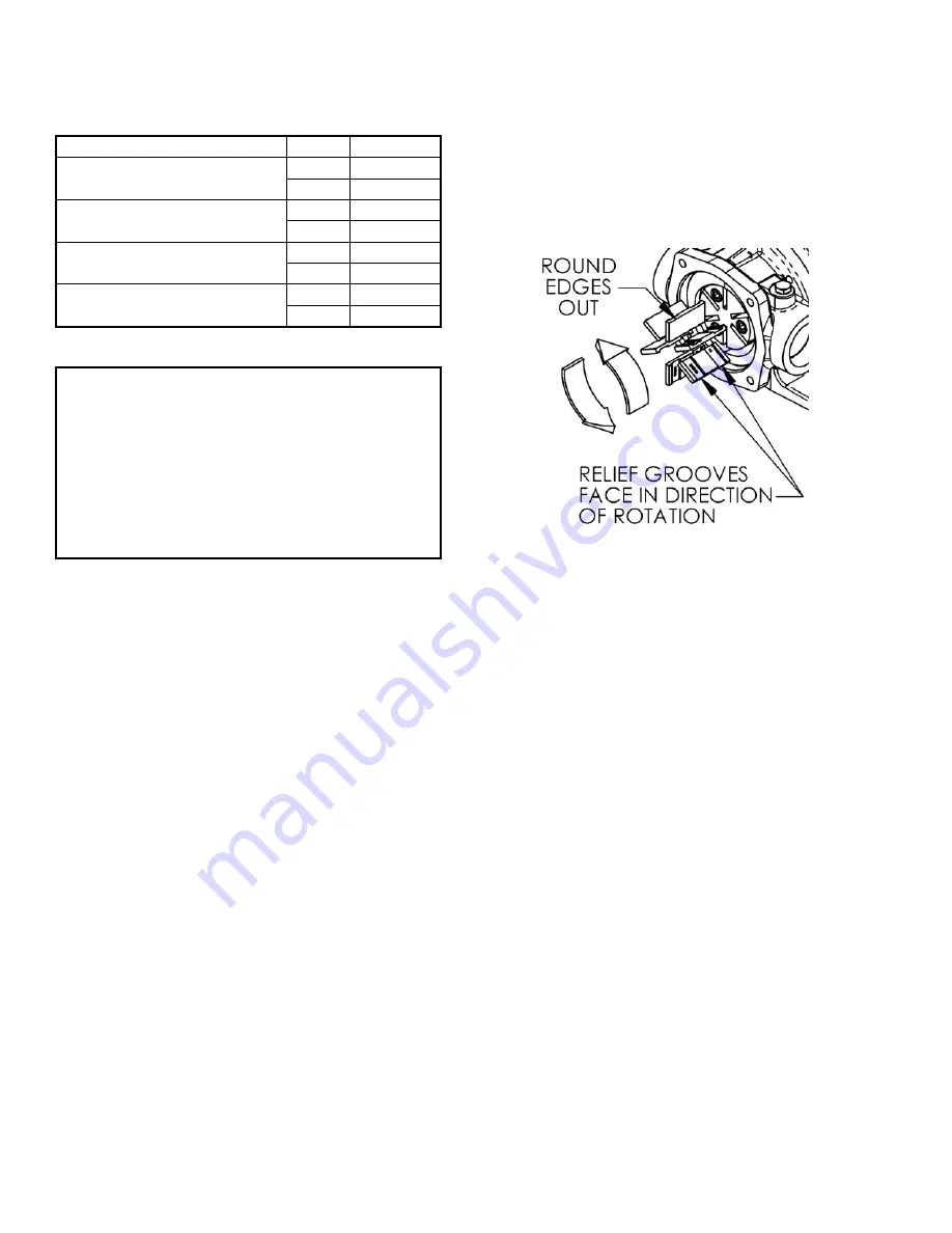
Figure 6 – Vane Replacement
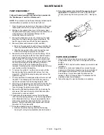
1. Flush the pump per instructions in this manual. Drain and
relieve pressure from the pump and system as required.
2. Remove the head cap screws (21). Gently pry the head
away from the casing using two screwdrivers. The head
O-ring should come off with the head assembly.
3. Turn the shaft by hand until a worn vane comes to the top
(12 o'clock) position of the rotor. Remove the vane.
4. Install a new vane, ensuring that the rounded edge is UP,
and the relief grooves are facing towards the direction of
rotation. See Figure 6.
5. Repeat steps 3 and 4 until all vanes have been replaced.
This method of vane installation ensures the push rods do
not fall out of their rotor slots.
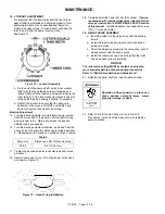
6. Carefully install the head (23) into the casing or cylinder.
Install and tighten four head cap screws (21). If equipped
with optional relief valve, to insure proper orientation see
Figures 4 and 5 in
Optional Pump Relief Valve
section
Torque per Table 1 shown at the beginning of the
maintenance section.
Summary of Contents for ProVane PV6B
Page 15: ...111 B00 Page 15 16 NOTES...


