background image

104-A00    Page 12/16 

MAINTENANCE 


Hazardous 

machinery can 

cause serious 

personal injury. 

Failure to stop the pump before 
adjusting the shaft packing can cause 
severe personal injury. 

9. 

PACKING ADJUSTMENT


Packing must be properly adjusted to prevent overheating. 

a.  While the liquid is being pumped, check for leakage 

from the stuffing box.  STOP the pump and uniformly 
tighten the packing follower stud nuts (18) 1/4 turn at 
a time to reduce leakage. 

b.  Restart the pump and check the stuffing box 

temperature several minutes after each adjustment 
for signs of overheating. 

c. 

Check the packing again after 20-30 minutes of 
running the pump, and readjust if necessary. 

NOTE: 

Some leakage is desirable to lubricate the 

packing, but in some cases is unacceptable, 
depending on the application. 

10.  BLACKMER TRIPLE-LIP SEAL (if equipped) 

On pumps equipped with a Blackmer triple-lip seal, refer to the 
separate literature accompanying the triple-lip seal for 
installation instructions. 

11.  COMMERCIAL MECHANICAL SEAL (if equipped) 

On pumps equipped with a commercial mechanical seal, refer 
to the separate literature accompanying the mechanical seal 
for installation instructions. 

12.  SHAFT SUPPORT BEARING (SNP3A  if equipped) 

a.  Screw the short threaded ends of the two hex studs 

(106E) firmly into the holes in the head. 

b.  Place the bearing flange (106) on the studs and tighten 

the locknuts (106A). 

c.  Slide the bearing and lock collar (106B) on the shaft 

until it is firmly seated in the bearing flange (106A). 

d.  Push inward on the bearing and lock collar (106B) 

while turning the lock collar by hand in the same 
direction as the shaft rotation. 

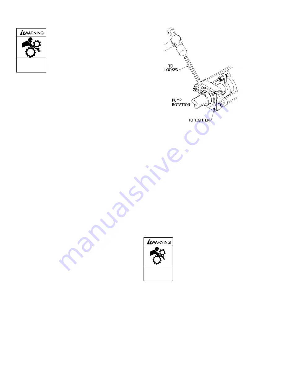
e.  Lock the collar to the shaft with a punch in the same 

direction as the shaft rotation.  See Fig. 11. 

f.  Bolt on the flange cover (106C). 

g.  If the shaft does not turn freely, loosen the lock collar 

and make sure the bearing is firmly seated in the 
bearing flange (106).  Re-tighten the lock collar. 


Figure 11 – Shaft Support Bearing Lock Collar 


13.  RELIEF VALVE ASSEMBLY (if equipped) 

a.  Insert the valve (9) into the relief valve body (6) with 

the fluted end inward. 

b.  Install the relief valve spring (8) and spring guide (7) 

against the valve. 

c. 

Attach a new relief valve gasket (10) and the valve 
cover (4) on the relief valve body (6). 

d.  Screw the relief valve adjusting screw (2) into the 

valve cover until it makes contact with the spring 
guide (7). 

e.  Install the relief valve cap (1) and gasket (88) after 

the relief valve has been precisely adjusted. 

NOTICE: 

The relief valve setting MUST be tested and 
adjusted more precisely before putting the pump 
into service.  Refer to "Relief Valve Setting and 
Adjustment" 

14.  Reinstall coupling, shaft key, and coupling guards. 
 

Do not operate 

without guard in 

place. 

Operation without guards in place can 
cause serious personal injury, major 
property damage, or death. 

 
15.  Refer to “Pre-Start Up Check List” and “Start Up 

Procedures” sections of this manual prior to pump 
operation. 


Summary of Contents for SNP1.25

Page 1: ...r s website www blackmer com or by contacting Blackmer Customer Service SAFETY DATA This is a SAFETY ALERT SYMBOL When you see this symbol on the product or in the manual look for one of the following...

Page 2: ...ion without guards in place can cause serious personal injury major property damage or death PUMP DATA PUMP IDENTIFICATION A pump Identification tag containing the pump serial number I D number and mo...

Page 3: ...piping system review the following suggestions 1 Locate the pump as near as possible to the source of supply to avoid excessive inlet pipe friction 2 The inlet line must be at least as large as the i...

Page 4: ...ermine direction of flow where the pump will be installed 2 Confirm pump is installed in piping so that the flow will pass through the pump from inlet to outlet The inlet of the pump has INLET cast in...

Page 5: ...es are fully open and that the drain valves and other auxiliary valves are closed 5 Install vacuum and pressure gauges on the pump in the 1 4 NPT connections provided These can be used to check actual...

Page 6: ...lve closed Bleed air into the pump through the intake gauge plug hole or through a larger auxiliary fitting in the intake piping Pump air for 30 second intervals to clean out most of the pumpage A dra...

Page 7: ...r a high suction lift and cavitation or starving of the pump exists partial closing of the discharge valve will result in excessive noise in the relief valve Plumbing the relief valve so flow is direc...

Page 8: ...rocedures and warnings as presented in this manual SCHEDULED MAINTENANCE STRAINERS Strainers must be cleaned regularly to avoid pump starvation Schedule will depend upon the application and conditions...

Page 9: ...SEAL OR A COMMERCIAL MECHANICAL SEAL a Loosen all setscrews before removing the head assembly For further instructions on the disassembly and assembly of commercial mechanical seals refer to the sepa...

Page 10: ...he notched end UP Align the notch in the bearing with the groove in the head See figure 7a c Using an arbor press press the bearing into the head in one continuous motion until it is flush with or sli...

Page 11: ...disc or shaft c Turn the shaft by hand until an empty slot comes to the 12 o clock position insert a vane and move on to the next slot 6 Place the inboard disc 71 and seal ring 72 on the cylinder 12 s...

Page 12: ...ighten the locknuts 106A c Slide the bearing and lock collar 106B on the shaft until it is firmly seated in the bearing flange 106A d Push inward on the bearing and lock collar 106B while turning the...

Page 13: ...om mating properly causing the rotor and shaft to bind or turn hard Use a tissue paper alcohol to clean the seal faces NOTE Apply a light oil or suitable lubricant to bronze seal faces only Other poss...

Page 14: ...he suction line Damaged or worn pump parts Too much lift for the vapor pressure of the fluid A dirty or clogged strainer Worn vanes Suction Valve Closed Incorrect pump rotation Relief Valve partially...

Page 15: ...104 A00 Page 15 16 NOTES...

Page 16: ...ess Marine Magnetic Drive Pumps Stainless Steel 14 to 215 GPM Abaque Peristaltic Hose Pumps 0 1 to 210 GPM High Lift Solids Abrasives Reciprocating Gas Compressors Liquefied Gas Transfer Boosting Vapo...

Reviews: