


104-A00 Page 9/16
MAINTENANCE
PUMP DISASSEMBLY
NOTICE:
Follow all hazard warnings and instructions provided in
the “Maintenance” section of this manual.
NOTE:
The numbers in parentheses following individual parts
indicate reference numbers on the Pump Parts List.
1. On the outboard (non-driven) side of the pump, remove
the head capscrews (21A), head (23) and disc (71).
Avoid damaging the head seal ring (72) and disc (71).
NOTE:
The sleeve bearing (bushing) (24) is press fit into
the head and should not be removed unless replacement
is necessary (see "Sleeve Bearings").
2. Turn the shaft by hand until a vane (14) comes to the top
(12 o'clock) position of the rotor. Remove each vane in
turn.
3. On the opposite (inboard) end of the pump, clean the
pump shaft thoroughly, making sure the shaft is free of
nicks, burrs, or paint that might damage the packing or
mechanical seal when the inboard head is removed.
4.
PUMPS EQUIPPED WITH PACKING
a. Remove the packing locknuts (18), studs (17) and
packing follower (75).
b. Remove the head capscrews (21), bracket (108),
head (20) and disc (71). Avoid damaging the head
seal ring (72) and disc (71).
NOTE:
The sleeve
bearing (24) is press fit into the head and should not
be removed unless replacement is necessary (see
"Sleeve Bearings").
c.
The packing rings (19) and packing washer (58) can
be pulled from the inboard hub with the use of a
corkscrew tool or screwdriver.
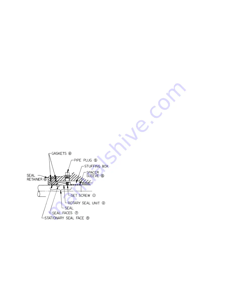
F i g u r e 6 – C o m m e r c i a l M e c h a n i c a l S e a l
5.
PUMPS EQUIPPED WITH BLACKMER TRIPLE-LIP
SEAL OR A COMMERCIAL MECHANICAL SEAL
a. Loosen all setscrews before removing the head
assembly. For further instructions on the
disassembly and assembly of commercial
mechanical seals, refer to the separate literature
accompanying the seal.
b. Remove the head capscrews (21), bracket (108),
head (20) and disc (71). Avoid damaging the head
seal ring (72) and disc (71).
NOTE:
The sleeve
bearing (24) is press fit into the head and should not
be removed unless replacement is necessary (see
"Sleeve Bearings").
6. From the driven side of the pump, grasp the rotor in the
3 and 9 o'clock positions, and gently pull the rotor and
shaft (13) out of the cylinder.
CAUTION:
Use care to
avoid injury-the rotor and shaft is heavy and may have
sharp edges.
PARTS REPLACEMENT
1. If any of the O-rings have been removed or disturbed
during disassembly, they must be replaced with new O-
rings.
NOTE:
PTFE O-rings should be heated in hot
water to aid installation.
2. Excessive or continuous leakage around the pump shaft
may be an indication of a damaged mechanical seal,
worn packing, or a damaged or worn sleeve bearing.
a. If a mechanical seal has been leaking, it is
recommended the entire seal be replaced. Refer to
"General Pump Troubleshooting" for possible
causes of seal leakage.
b. If the packing is leaking excessively, refer to
"Packing Adjustment." If this does not solve the
problem, a complete new set of packing rings
should be installed.
c.
If the pump shaft indicates an excessive amount of
radial "play," the sleeve bearing in the hub should be
replaced.
3. Worn or scored discs may be reused if interchanged
from one head to the other with the new side toward the
rotor.
Summary of Contents for SNP1.25
Page 15: ...104 A00 Page 15 16 NOTES...


