

101-A00 page 3/12
INSTALLATION
NOTICE:
Blackmer pumps must only be installed in systems
designed by qualified engineering personnel. System
design must conform with all applicable regulations and
codes and provide warning of all system hazards.
Install, ground and wire to local and
National Electrical Code requirements.
Install an all-leg disconnect switch near
the unit motor.
Disconnect and lockout electrical power
before installation or service
Electrical supply MUST match motor
nameplate specifications.
Hazardous voltage.
Can shock, burn or
cause death.
Motors equipped with thermal protection automatically
disconnect motor electrical circuit when overload exists.
Motor can start unexpectedly and without warning.
PRE-INSTALLATION CLEANING
NOTICE:
New pumps contain residual test fluid and rust inhibitor.
If necessary, flush pump prior to use.
Foreign matter entering the pump WILL cause extensive
damage. The supply tank and intake piping MUST be
cleaned and flushed prior to pump installation and operation.
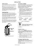
LOCATION AND PIPING
Pump life and performance will be significantly reduced when
installed in an improperly designed system. Before starting
the layout and installation of the piping system, review the
following suggestions:
1. Locate the pump as near as possible to the source of
supply to avoid excessive inlet pipe friction.
2. The inlet line should be at least as large as the intake
port on the pump. It should slope downward to the
pump, and should not contain any upward loops.
Eliminate restrictions such as sharp bends; globe valves,
unnecessary elbows, and undersized strainers.
3. A strainer must be installed in the inlet line to protect the
pump from foreign matter. The strainer should be
located at least 24" (0.6m) from the pump, and have a
net open area of at least four times the area of the intake
piping. Strainers must be cleaned regularly to avoid
pump starvation.
4. The intake and discharge piping system must be free of
all leaks.
5. Expansion joints, placed at least 36" (0.9m) from the
pump, will compensate for expansion and contraction of
the pipes. Contact the flexible connector/hose
manufacturer for required maintenance/care and design
assistance in their use.
6.
Install pressure gauges in the NPT ports provided in the
pump casing to check pump performance at start up.
7. ALL piping and fittings MUST be properly supported to
prevent any piping loads from being placed on the pump.
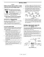
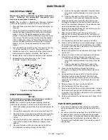
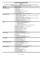
8. Check alignment of pipes to pump to avoid strains,
which might later cause misalignment. See Figure 2.
Unbolt flanges or break union joints. Pipes should not
spring away or drop down. After pump has been in
operation for a week or two, completely recheck
alignment.
Figure 2
9. When pumping liquids at elevated temperature,
provisions should be made to compensate for expansion
and contraction of the pipes, especially when long pipe
lines are necessary. Steel pipe expands approximately
3/4” (1.9 cm) per 100 feet (30.49 m) per 100°F (37.8°C)
rise in temperature.
INTERNAL PUMP RELIEF VALVE AND
BACK TO TANK BYPASS VALVE
NOTICE:
The pump internal relief valve is designed to protect the
pump from excessive pressure and must not be used as
a system pressure control valve.
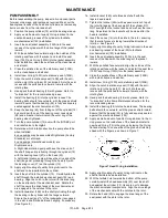
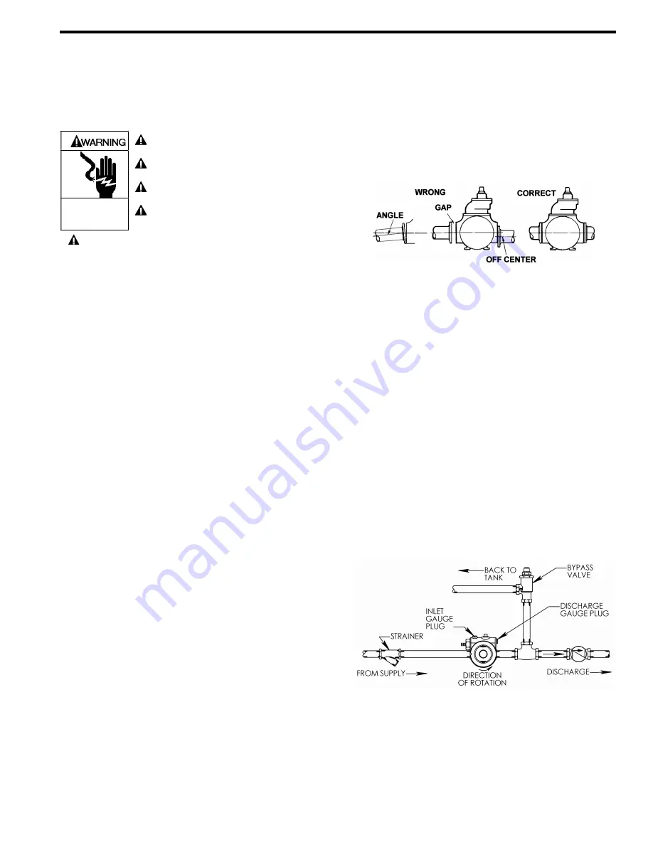
Pumping volatile liquids under suction lift may cause
cavitation. Partial closing of the discharge valve WILL result
in internal relief valve chatter and is NOT recommended. For
these applications, install an external system pressure
control valve, and any necessary bypass piping, back to the
storage tank. See Figure 3
A system pressure control valve is also recommended when
operating for extended periods (more than 1 minute) against
a closed discharge valve.
Figure 3
Bypass Valve Mounting
Summary of Contents for XB1A
Page 11: ...101 A00 Page 11 12 NOTES...


