
101-A00 Page 5/12
OPERATION
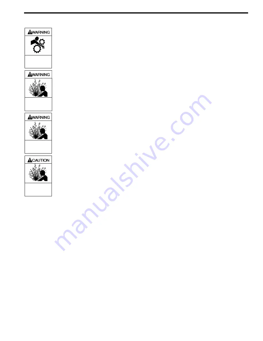
Operation without guards in place can
cause serious personal injury, major
property damage, or death.
Do not operate
without guard
in place
Disconnecting
fluid
or
pressure
containment components during pump
operation can cause serious personal
injury, death or major property damage
Hazardous pressure
can cause personal
injury or property
damage
Failure to relieve system pressure prior
to performing pump service or
maintenance can cause serious
personal injury or property damage.
Hazardous pressure
can cause serious
personal injury or
property damage
Pumps operating against a closed valve
can cause system failure, personal
injury and property damage
Hazardous pressure
can cause personal
injury or property
damage
PRE-START UP CHECK LIST
1. Check the alignment of the pipes to the pump. Pipes
should be supported so that they do not spring away or
drop down when pump flanges or union joints are
disconnected.
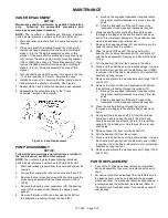
2. Verify proper coupling alignment.
3. Check the entire pumping system to verify that the
proper inlet and discharge valves are fully open, and that
the drain valves and other auxiliary valves are closed.
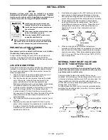
4. Install suction and discharge pressure gauges on the
pump in the 1/4” NPT connections provided.
5. Check the wiring of the motor.
6. Briefly start the pump to verify proper rotation direction.
START UP PROCEDURES
NOTICE:
Consult the "General Pump Troubleshooting" section of
this manual if difficulties during start up are
experienced.
1. Start the pump. Priming should occur within one minute.
2. Check the vacuum and pressure gauges to ensure the
pump is operating within the expected conditions.
3. Inspect piping, fittings, and associated system
equipment for leaks, noise, vibration and overheating.
4. If possible, check the flow rate to ensure the pump is
operating within the expected parameters. Record flow
rate in the “Initial Startup Information” section.
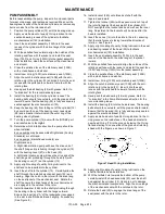
5. Check the pressure setting of the relief valve by
momentarily closing a valve in the discharge line and
reading the pressure gauge. This pressure should be 10
– 20 psi (.7 – 1.4 bar) higher than the maximum system
operating pressure, or the external system pressure
control valve setting (if equipped).
DO NOT operate the
pump against a closed discharge valve for more
than 15 seconds.
If adjustments need to be made,
refer to “Relief Valve Setting and Adjustment” section of
this manual.
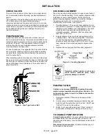
FLUSHING THE PUMP
NOTICE:
If flushing fluid is to be left in the pump for an extended
time, it must be a lubricating, non-corrosive fluid. If a
corrosive or non-lubricating fluid is used, it must be
flushed from the pump immediately.
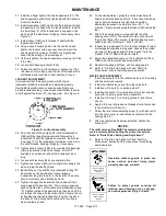
1. To flush the pump, run the pump with the discharge
valve open and the intake valve closed. Bleed air into
the pump through the intake gauge plug hole or through
a larger auxiliary fitting in the intake piping. Pump air for
30 second intervals to clean out most of the pumpage.
2. Run a system compatible flushing fluid through the pump
for one minute to clear out the remainder of the original
pumpage.
3. To remove the flushing fluid, follow step 1.
NOTICE:
After flushing, some residual fluid will remain in the
pump and piping.
NOTICE:
Properly dispose of all waste fluids in accordance
with the appropriate codes and regulations.
Summary of Contents for XB1A
Page 11: ...101 A00 Page 11 12 NOTES...


