
101-A00 Page 8/12
MAINTENANCE
PUMP ASSEMBLY
Before reassembling the pump, inspect all component parts
for wear or damage, and replace as required. Wash out the
bearing/seal recess of the head and cylinder and remove any
burrs or nicks from the rotor and shaft.
1. Position the pump cylinder (12) with the bearing side up.
2. Apply a small amount of quality O-ring lubricant in the
seal and bearing recess of the cylinder to facilitate
mechanical seal (153) installation.
3. Insert the seal jacket assembly (153A) into the seal
recess of the cylinder with the drive tangs of the jacket
inward.
4. With the polished face outward, align the notches of the
rotating seal face with the jacket, and install the seal
face (153F) and O-ring (153G) into the jacket assembly.
After installation, clean the seal face with a clean tissue
and alcohol.
5. Clean the polished face of the stationary seat (153B)
with a clean tissue and alcohol.
6. Install new O-ring (153D) onto stationary seat (153B).
7. Align the notch in stationary seat (153B) with the anti-
rotation pin in the cylinder (12) and insert it into the seal
recess with the polished face inward to mate with the
rotating face.
8. Hand pack the ball bearing (24) with grease. Refer to
"Lubrication" for the recommended grease.
9. Install the bearing (24) into the cylinder recess. The
bearing balls should face outward, with the grease shield
inward. Ensure that the bearing (24) is fully and squarely
seated against the mechanical seal (153).
10. Keep the bearing (24) from falling out of the cylinder (12)
by securing with one of the bearing cover capscrews
(28) and a washer that will catch the outer ring of the
bearing when tightened.
11. Turn the pump cylinder (12) over with the INTAKE port
and relief valve to the
right
.
12. Determine which rotation direction the pump should be
when installed.
6 vane pumps may be assembled Right-Hand (Factory
Standard) or Left-Hand.
4 vane pumps (discontinued models) are
Right Hand only.
A Right-Hand rotation pump will have the drive end of
the shaft (long end) protruding through the cylinder (12)
with the bearing cover (27) on the head (20).
A Left-Hand rotation pump will have the drive end of the
shaft (long end) protruding through the head (20) with
the bearing cover (27) on the cylinder (12).
13. Apply a light coating of quality O-ring lubricant to the
shaft end to be inserted into the cylinder.
14. Insert the shaft into the cylinder (12). Carefully slide the
shaft through the installed mechanical seal (153) and
bearing. Align the notch in the rotor with the drive tang
on the seal jacket of the mechanical seal. Rotate the
shaft to ensure the drive tangs of the mechanical seal
are engaged in the notches in the rotor.
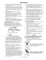
15. Install lockwasher (24B) on the shaft protruding through
the bearing in the cylinder with the tangs outward.
Ensure the inner tang “A” of the lockwasher is engaged
in the slot in shaft threads. Bend it slightly, if necessary.
(See Figure 8.)
16. Install locknut (24A) onto threads of shaft with the
tapered end inward.
17. Tighten the locknut (24A) with a spanner wrench to pull
the rotor flat against the back wall of the cylinder. DO
NOT overtighten the locknut and bend or shear the inner
tang. Adjustment to the locknuts will be made after the
head is installed.
18. Insert the vanes (14) into the slots in the rotor, ensuring
that the relief groove is facing toward the direction of
rotation. See Figure 6
19. Apply a light coating of quality O-ring lubricant in the seal
and bearing recess of the head (20) to facilitate
mechanical seal (153) installation.
20. Insert the seal jacket assembly (153A) into the seal
recess of the head with the drive tangs of the jacket
inward.
21. With the polished face outward, align the notches of the
rotating seal face with the jacket, and install the seal face
(153F) and O-ring (153G) into the jacket assembly.
22. Clean the polished face of the stationary seat (153B)
with a clean tissue and alcohol.
23. Install new O-ring (153D) onto stationary seat (153B).
24. Align the notch in stationary seat (153B) with the anti-
rotation pin in the head (20). Insert it into the seal
recess with the polished face inward to mate with the
rotating face.
25. Hand pack the ball bearing (24) with grease. Refer to
"Lubrication" in the Pump Maintenance Section for the
recommended grease.
26. Install the bearing (24) into the head recess. The bearing
balls should face outward, with the grease shield inward.
Ensure that the bearing (24) is fully and squarely seated
against the mechanical seal (153).
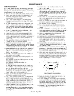
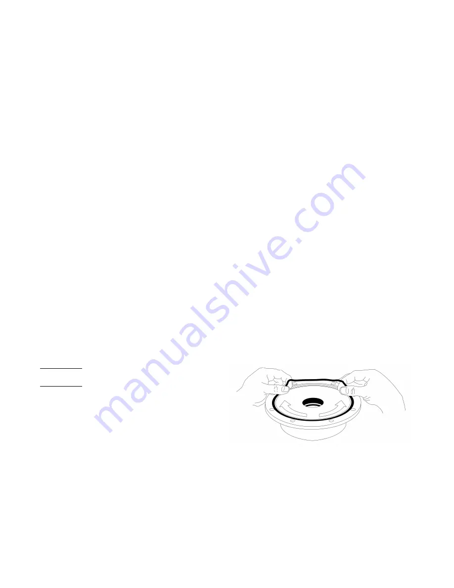
27. Apply a small amount of quality O-ring lubricant to the O-
ring groove on the inside face of the head and install a
new head O-ring (72) in the groove by laying the O-ring
flat and starting in on one side of the groove, stretching
ahead with the fingers, as shown in Figure 7.
Figure 7 Head O-ring Installation
28. Apply a light coating of quality O-ring lubricant on the
shaft to facilitate head installation.
29. With the telltale hole towards the bottom of the pump,
carefully install the head assembly (20) over the shaft
and against the cylinder (12). Use care not to damage
the mechanical seal components. Align the drive tangs
of the mechanical seal with the notches in the rotor.
30. Rotate the head (20) to engage the drive tangs of the
seal jacket with the slots in the rotor.
Summary of Contents for XB1A
Page 11: ...101 A00 Page 11 12 NOTES...


