101-A00 Page 9/12
MAINTENANCE
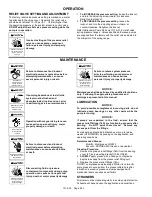
31. Install and finger tighten the head capscrews (21). The
head capscrews will be fully tightened after the second
locknut is installed.
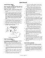
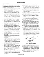
32. Install lockwasher (24B) on the shaft protruding through
the bearing in the head with the tangs outward. Ensure
the inner tang “A” of the lockwasher is engaged in the
slot in shaft threads. Bend it slightly, if necessary. (See
Figure 8.)
33. Install locknut (24A) onto threads of shaft with the
tapered end inward.
34. Using a keyed coupling half, hold the shaft end and
tighten the locknut with a spanner wrench to pull the
head against the cylinder. DO NOT overtighten and
shear the inner tang of the lockwasher.
35. Uniformly tighten the head capscrews, torquing to 25 lbs
ft (34 Nm).
36. Loosen both bearing locknuts (24A).
37. Rotate the shaft to test for binding or tight spots. If the
rotor does not turn freely, tap the rim of the head with a
soft-faced mallet until the correct position is found.
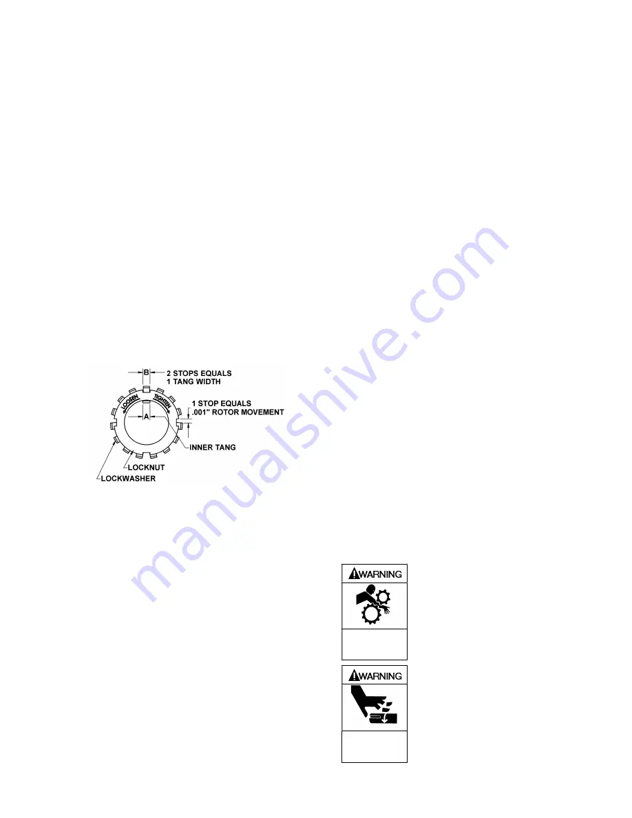
LOCKNUT ADJUSTMENT
It is important that the bearing locknuts (24A) and
lockwashers (24B) be installed and adjusted properly.
Overtightening locknuts can cause bearing failure or a
broken lockwasher tang. Loose locknuts will allow the rotor
to shift against the discs (71), causing wear. See Figure 8.
Figure 8– Locknut Assembly
38. On both ends of the pump shaft, install a lockwasher
(24B) with the tangs facing outward, followed by a
locknut (24A) with the tapered end inward. Ensure the
inner tang "A" of the lockwasher is located in the slot in
the shaft threads, bending it slightly, if necessary.
39. Tighten both locknuts (24B) to ensure that the bearings
(24) are bottomed in the head recess. DO NOT
overtighten and bend or shear the lockwasher inner
tang.
40. Loosen both locknuts (24A) one complete turn.
41. Tighten one locknut (24A) until a slight rotor drag is felt
when turning the shaft by hand.
42. Back off the nut the width of one lockwasher tang "B".
Secure the nut by bending the closest aligned
lockwasher tang into the slot in the locknut. The pump
should turn freely when rotated by hand.
43. Tighten the opposite locknut (24A) by hand until it is
snug against the bearing (24). Then, using a spanner
wrench, tighten the nut the width of one lockwasher tang
“B”. Tighten just past the desired tang, then back off the
nut to align the tang with the locknut slot. Secure the nut
by bending the aligned lockwasher tang into the slot in
the locknut. The pump should continue to turn freely
when rotated by hand.
44. To check adjustment, grasp the nut and washer with
fingers and rotate back and forth. If this cannot be done,
one or both locknuts are too tight and should be
alternately loosened one stop at a time (.001" - 25
microns). Begin by loosening the locknut (24A) adjusted
last.
45. Attach the new bearing cover gasket (26) and the
bearing cover (27) to the non-driven side of pump with
the grease fitting (76) upward. Install the bearing cover
capscrews (28), torquing to 15 lbs ft (20 Nm).
46. Inspect the grease seal (104) in the foot bracket for wear
or damage and replace as required. Grease the outside
diameter of the grease seal (104) and push it into the
bracket (108 or 108B) with the lip inward.
47. Mount the assembled pump on the foot bracket (108 or
108B) with the four mounting screws (28A).
48. Reinstall coupling, shaft key, and coupling guards.
49. Refer to “Pre-Start Up Check List” and “Start Up
Procedures” prior to restarting pump operation.
RELIEF VALVE ASSEMBLY
1. Insert the valve (9) into the relief valve bore of the casing
with the small end inward.
2. Install the relief valve spring (8) in the valve bore.
3. Install new O-ring (4A) on spring guide (7).
4. Install spring guide (7) in valve bore of cylinder, aligning
spring (8) on spring guide during assembly.
5. Install new O-ring (10) in O-ring groove in relief valve
cap (4).
6. Apply a thin coat of grease on threads of relief valve cap
(4) and install in cylinder (12).
7. Screw the relief valve adjusting screw (2) with locknut (3)
into the valve cover (4) until it makes contact with the
spring guide (7).
8. After the relief valve has been adjusted, tighten the
Locknut (3)
NOTICE:
The relief valve setting MUST be tested and adjusted
more precisely before putting the pump into service.
Refer to "Relief Valve Setting and Adjustment"
9. Refer to “Pre-Start Up Check List” and “Start Up
Procedures” sections of this manual prior to restarting
pump operation.
Operation without guards in place can
cause serious personal injury, major
property damage, or death.
Do not operate
without guard
in place
Failure to adjust guards covering all
rotating part, allowing only a safe gap,
can cause personal injury or death
Do not operate
without guard
in place
Summary of Contents for XB1A
Page 11: ...101 A00 Page 11 12 NOTES...


