background image

107-B00    Page 3/16 

INSTALLATION

PRE-INSTALLATION CLEANING 

NOTICE: 

New pumps contain residual test fluid and rust inhibitor.  
If necessary, flush pump prior to use. 

Foreign matter entering the pump WILL cause extensive 
damage.  The supply tank and intake piping MUST be 
cleaned and flushed prior to pump installation and operation. 


LOCATION AND PIPING 

Pump life and performance can be significantly reduced when 
installed in an improperly designed system. Before starting 
the layout and installation of the piping system, review the 
following: 

1.  Locate the pump as near as possible to the source of 

supply to avoid excessive inlet pipe friction. 

2.  The inlet line MUST be at least as large as the intake 

port on the pump. It should slope downward to the pump, 
and should not contain any upward loops. Eliminate 
restrictions such as sharp bends; globe valves, 
unnecessary elbows, and undersized strainers. 

3.  It is recommended a strainer be installed in the inlet line 

to protect the pump from foreign matter. The strainer 
should be located at least 24" (0.6m) from the pump, and 
have a net open area of at least four times the area of 
the intake piping. Strainers must be cleaned regularly to 
avoid pump starvation. 

4.  The intake system must be free of air leaks. 

5.  Expansion joints, placed at least 36" (0.9m) from the 

pump, will compensate for expansion and contraction of 
the pipes. Contact the flexible connector/hose 
manufacturer for required maintenance/care and design 
assistance in their use. 

6. 

Install pressure gauges in the NPT ports provided in the 
pump casing to check pump at start up.


7.  ALL piping and fittings MUST be properly supported to 

prevent any piping loads from being placed on the pump. 

8.  Check alignment of pipes to pump to avoid strains which 

might later cause misalignment.  See Figure 1.  Unbolt 
flanges or break union joints.  Pipes should not spring 
away or drop down.  After pump has been in operation 
for a week or two, completely recheck alignment. 


Figure 1 

9.  When pumping liquids at elevated temperature, 

provisions should be made to compensate for expansion 
and contraction of the pipes, especially when long pipe 
lines are necessary.  Steel pipe expands approximately 
3/4” (1.9 cm) per 100 feet (30.49 m) per 100°F (37.8°C) 
rise in temperature. 
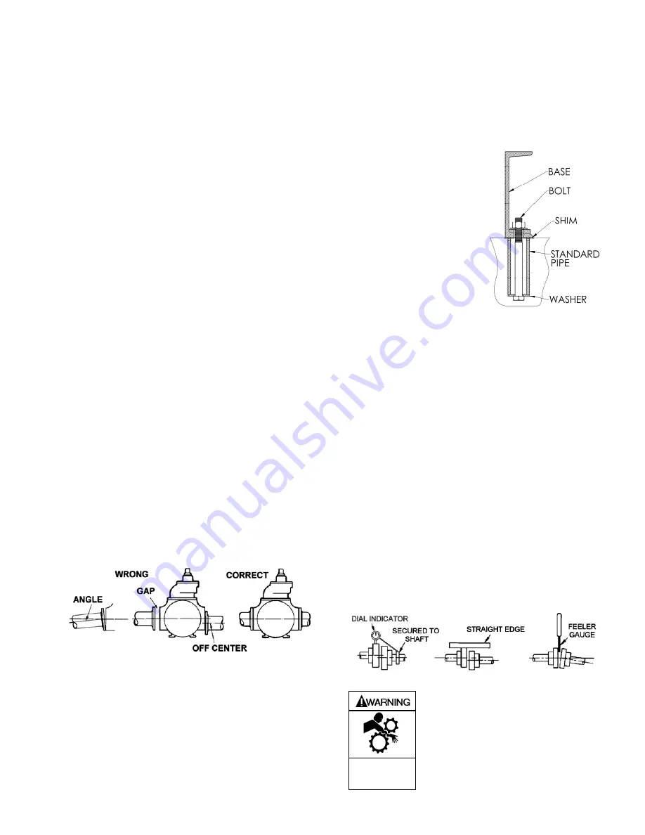
 

PUMP MOUNTING 

A solid foundation reduces noise and vibration, and will 
improve pump performance. On permanent installations it is 
recommended the pumping unit be secured by anchor bolts 
as shown in Figure 2. This arrangement allows for slight 
shifting of position to accommodate alignment with the 
mounting holes in the base plate. 
 

         Figure 2 - Pipe Type 
               Anchor Bolt Box


For new foundations, it is 
suggested that the anchor 
bolts be set in concrete. 
When pumps are to be 
located on existing concrete 
floors, holes should be 
drilled into the concrete to 
hold the anchor bolts. 

When installing units built on 
channel or structural steel 
type bases, use care to 
avoid twisting the base out of 
shape when anchor bolts are tightened. Shims should be 
used under the edges of the base prior to tightening of the 
anchor bolts to prevent distortion. 
 

COUPLING ALIGNMENT 

The pump must be directly coupled to a gear and/or driver 
with a flexible coupling.  Verify coupling alignment after 
installation of new or rebuilt pumps.  Both angular and 
parallel coupling alignment MUST be maintained between the 
pump, gear, motor, etc. in accordance with manufacturer’s 
instructions.  See Figure 3. 

1.  Parallel alignment:  The use of a laser alignment tool or 

dial indicator is preferred.  If a laser alignment tool or dial 
indicator is not available, use a straightedge.  Turn both 
shafts by hand, checking the reading through one 
complete revolution.  Maximum offset should be less 
than .005" (.127 mm). 

2.  Angular alignment:  Insert a feeler gauge between the 

coupling halves.  Check the spacing at 90° increments 
around the coupling (four checkpoints).  Maximum 
variation should not exceed .005" (.127 mm).  Some 
laser alignment tools will check angular alignment as 
well. 

3.  Replace the coupling guards after setting alignment. 


Figure 3 – Alignment Check 


Operation without guards in place can 
cause serious personal injury, major 
property damage, or death. 


Do not operate 

without guard 

in place 

Summary of Contents for XL2B

Page 1: ... inch 107 B01 107 B02 SAFETY DATA This is a SAFETY ALERT SYMBOL When you see this symbol on the product or in the manual look for one of the following signal words and be alert to the potential for personal injury death or major property damage Warns of hazards that WILL cause serious personal injury death or major property damage Warns of hazards that CAN cause serious personal injury death or ma...

Page 2: ...ference If replacement parts are needed or if information pertaining to the pump is required this data must be furnished to a Blackmer representative TECHNICAL DATA 2 3 inch 4 inch Maximum Pump Speed 780RPM 640 RPM Maximum Operating Temperature 240 F 115 C Maximum Differential Pressure 150 psi 10 3 Bar Maximum Working Pressure 350 psi 24 1 Bar Technical Data is for standard materials of constructi...

Page 3: ...t elevated temperature provisions should be made to compensate for expansion and contraction of the pipes especially when long pipe lines are necessary Steel pipe expands approximately 3 4 1 9 cm per 100 feet 30 49 m per 100 F 37 8 C rise in temperature PUMP MOUNTING A solid foundation reduces noise and vibration and will improve pump performance On permanent installations it is recommended the pu...

Page 4: ...ry death or major property damage Hazardous pressure can cause personal injury or property damage Failure to relieve system pressure prior to performing pump service or maintenance can cause personal injury or property damage Hazardous pressure can cause personal injury or property damage Pumps operating against a closed valve can cause system failure personal injury and property damage Hazardous ...

Page 5: ... within the expected conditions Record pressures in the Initial Start Up Information section 3 Check for leakage from the piping and equipment 4 Check for overheating excessive noise or vibration of the pump reducer and motor 5 Check the flow rate to ensure the pump is operating within the expected parameters Record flow rate in the Initial Start Up Information section 6 Check the pressure setting...

Page 6: ...sure control valve XL series pumps are fitted with an internal pressure relief valve that bypasses back to the suction side of the pump Pumping volatile liquids under suction lift may cause cavitation Partial closing of the discharge valve WILL result in internal relief valve chatter and is NOT recommended For these applications install an external system pressure control valve and any necessary b...

Page 7: ... avoid possible entanglement in moving parts do not lubricate pump bearings gear reducer or any other parts while the pump is running NOTICE If pumps are repainted in the field ensure that the grease relief fittings 76A are functioning properly after painting Do NOT paint them closed Remove any excess paint from the fittings Pump bearings should be lubricated every one to twelve weeks AT MINIMUM d...

Page 8: ...or damage and replace as required c Repeat steps a and b on the opposite shaft end 6 Remove the head capscrews 21 Gently pry the head away from the casing using two large screwdrivers The head O ring should come off with the head assembly 7 Slide the head and O ring off the shaft The bearing 24 mechanical seal stationary seat and stationary O ring 153A 153D will come off with the head assembly a O...

Page 9: ...bottom vanes and push rods are installed carefully insert the non driven end of rotor and shaft into the casing d Install the remaining vanes into the top positions of the rotor 7 DISC 2 and 3 inch Models Install the disc 71 on the inboard side of the pump with the seal cavity facing outward and the disc relief hole located as shown in Figure 6 Figure 6 Disc Relief Hole Location 2 and 3 inch Model...

Page 10: ...he head capscrews to 30 lbs ft 40 7 Nm alternating between one side of the head and the other Frequently check that the shaft still turns freely If tight loosen the capscrews and repeat the procedure If the shaft continues to bind check for grease or dirt on the mechanical seal faces Figure 9 Locknut Assembly 20 LOCKNUT ADJUSTMENT It is important that the bearing locknuts 24A and lockwashers 24B b...

Page 11: ...uide 7 against the valve c Attach a new relief valve O ring 10 and the valve cover 4 on the cylinder d Screw the relief valve adjusting screw 2 with locknut 3 into the valve cover 4 until it makes contact with the spring guide 7 e After the relief valve has been adjusted tighten the Locknut 3 and install the relief valve cap 1 and O ring 88 NOTICE The relief valve setting MUST be tested and adjust...

Page 12: ...otor and brake windings to verify the integrity of the winding insulation and inspect all terminal box openings and wire connection areas to verify that all components are dry and free of corrosion Long Term Storage By taking special precautions problems such as seal leakage and reducer failure due to the lack of lubrication improper lubrication quantity or contamination can be avoided The followi...

Page 13: ...alphaolefin Oil FG Food Grade Oil NOTICE The Ambient Temperature is intended to be an operation guideline based upon the typical properties of all the lubricant The viscosity and other properties of the lubricant change based upon load speed ambient conditions and reducer operating temperatures The user should consult with their lubrication supplier NORD gear before considering changes in oil type...

Page 14: ...Liquids that set up when inactive OVERHEATING Probable Cause Corrective Action Continual full bypassing of the liquid Adjust the relief valve such that the pump will not bypass during normal operation WARNING Internal bypassing of liquid elevates the liquid temperature The internal bypass valve should only be used for brief periods and at differential pressures below 125 psi For extended periods o...

Page 15: ...rn vanes discs or rotor Bearing Worn or Damaged Loose or improperly installed piping Misalignment of pump and driver or bent shaft Pump base not properly mounted Insufficient Oil in the Gear Reducer POOR OR NO PRIMING Probable Cause Air leaks in the suction line Valve partially closed or other restriction in the suction line Damaged or worn pump parts Too much lift for the vapor pressure of the fl...

Page 16: ...cked cut or twisted Shaft at seal area damaged worn or dirty Excessive cavitation Mechanical seal faces cracked scratched pitted or dirty Ball bearings overgreased MOTOR OVERLOAD Probable Cause Horsepower of motor not sufficient for application Improper wire size wiring and or voltage to motor Misalignment in pump drive system Bearing locknuts adjusted improperly Excessive viscosity pressure or sp...

Reviews: