


105-A00 page 4/12
INSTALLATION
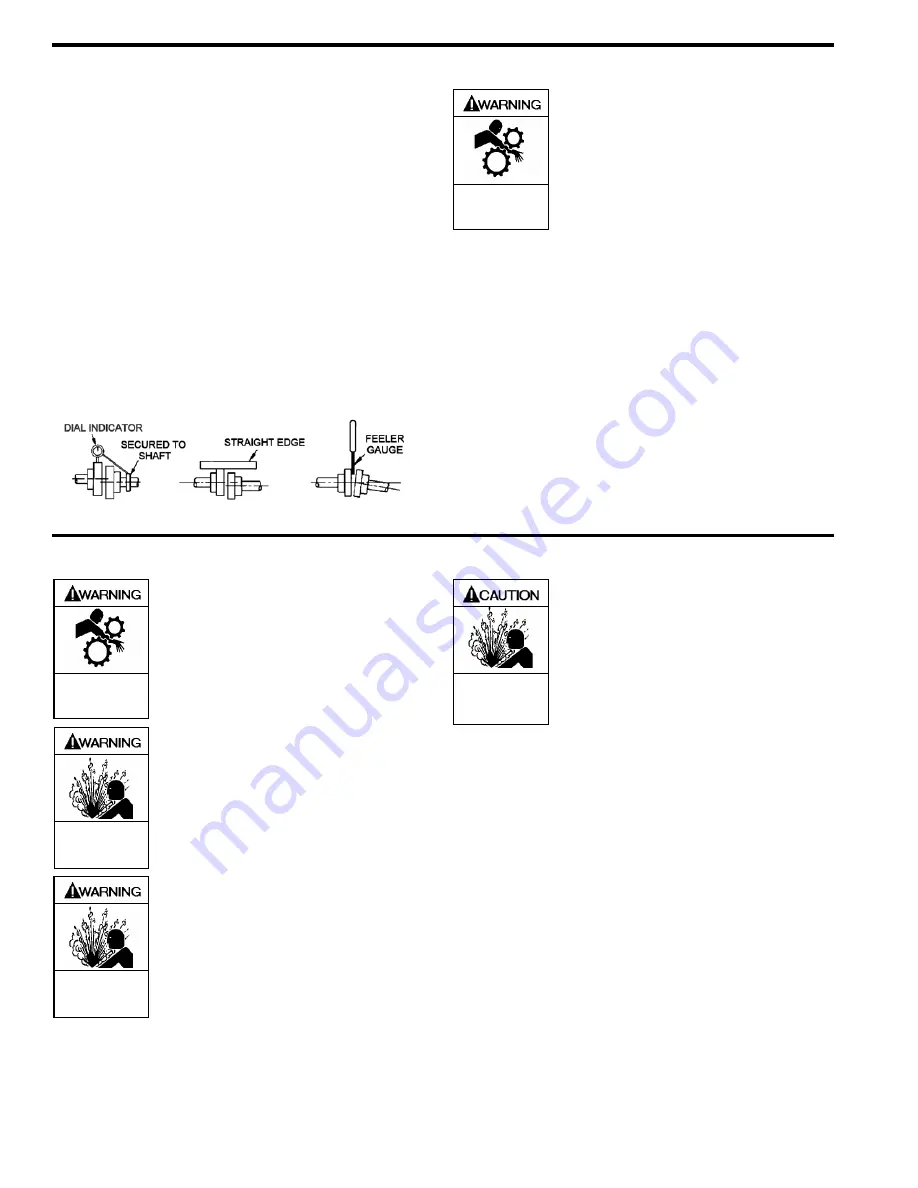
COUPLING ALIGNMENT
The pump must be directly coupled to a gear reducer and/or
driver with a flexible coupling. Both angular and parallel
coupling alignment MUST be maintained between the pump,
gear, motor, etc. in accordance with manufacturer’s
instructions. See Figure 4.
1. Parallel alignment: The use of a laser alignment tool or
dial indicator is preferred. If a laser alignment tool or
dial indicator is not available, use a straightedge. Turn
both shafts by hand, checking the reading through one
complete revolution. Maximum offset should be less
than .0005" (0.127 mm).
2. Angular alignment: Insert a feeler gauge between the
coupling halves. Check the spacing at 90° increments
around the coupling (four checkpoints). Maximum
variation should not exceed 0.005" (0.127 mm). Some
laser alignment tools will check angular alignment as
well.
3. Replace the coupling guards after setting alignment.
Figure 4 – Coupling Alignment
Do not operate
without guard
in place
OPERATION WITHOUT GUARDS IN
PLACE CAN CAUSE SERIOUS
PERSONAL INJURY, MAJOR
PROPERTY DAMAGE, OR DEATH.
PUMP ROTATION
NOTICE:
CONFIRM CORRECT PUMP ROTATION BY CHECKING
THE PUMP ROTATION ARROWS RESPECTIVE TO PUMP
DRIVER ROTATION.
TO CHANGE PUMP ROTATION
To reverse rotation, the pump must be disassembled then
reassembled with the shaft on the opposite side of the pump.
See the ‘Maintenance’ section for instructions.
OPERATION
Do not operate
without guard
in place
OPERATION WITHOUT GUARDS IN
PLACE CAN CAUSE SERIOUS
PERSONAL INJURY, MAJOR
PROPERTY DAMAGE, OR DEATH.
Hazardous pressure
can cause personal
injury or property
damage
DISCONNECTING FLUID OR PRESSURE
CONTAINMENT COMPONENTS DURING
PUMP OPERATION CAN CAUSE
SERIOUS PERSONAL INJURY, DEATH
OR MAJOR PROPERTY DAMAGE.
Hazardous pressure
can cause personal
injury or property
damage
FAILURE TO RELIEVE SYSTEM
PRESSURE PRIOR TO PERFORMING
PUMP SERVICE OR MAINTENANCE
CAN CAUSE PERSONAL INJURY OR
PROPERTY DAMAGE.
Hazardous pressure
can cause personal
injury or property
damage
PUMPS OPERATING AGAINST A
CLOSED VALVE CAN CAUSE SYSTEM
FAILURE, PERSONAL INJURY AND
PROPERTY DAMAGE
PRE-START UP CHECK LIST
1. Check the alignment of the pipes to the pump. Pipes
should be supported so that they do not spring away or
drop down when pump flanges or union joints are
disconnected.
2. Check the entire pumping system to verify that the proper
inlet and discharge valves are fully open, and that the
drain valves and other auxiliary valves are closed.
3. Install suction and discharge pressure gauges on the
pump in the threaded connections provided. These can be
used to check actual suction and discharge conditions
after pump start-up.
4. Check the wiring of the motor.
5. Briefly start the pump to verify proper rotation direction.
Summary of Contents for XLW1 1/2
Page 11: ...105 A00 Page 11 12 NOTES...


